Abstract
Strip mill vibration greatly affects the quality of products, rolling productivity, and even cause strip broken or equipment damage. In order to explore the serious vibration phenomena occured in CSP (Compact Strip Production) hot strip mill when rolling thin container strips, in this paper we established a mill main drive system nonlinear torsional vibration model, and emphatically studied the influence of rolling load, multi-stand coupling (tension) and interface friction on the torsional vibration of the system; Based on numerical simulation, field measurement and signal time-frequency analysis (Wigner-Ville distribution), we analyzed the mills torsional vibration and horizontal vibration characteristics, the influence of multi-stand coupling (tension) on the rolls torsional vibration.
1. Introduction
Hot strip mill is a large complex integration equipment, there are a variety of complex coupling between systems and the process of rolling mill, in certain conditions or disturbances of rolling process, it is easy to induce varying degrees vibration and these vibration problems severely limit the quality and productivity of rolling strip products, and severe vibration may cause strip broken or equipment damage, which has serious threat to safety and causes huge economic losses. Despite there have extensive research, but due to the complexity of the issue, which has not been solved perfectly.
A. Bar presented the numerical analysis of vibrations with moderate frequencies excited during the milling process taking into account the transportation motion of the strip and its inertial properties [1]. Yongjiang Zheng carried out a complete spatial vibration characteristic analysis based on the modified Riccati-overall transfer matrix method and coupled vibration characteristics of cross and sway motions along with the complex mode shape analysis of the mills [2]. Adam Bar built the non-linear mathematical model of oscillated system: the continuous group of the rolling stands coupled by transferring strip [3]. Pei-Hua studied three-stand tandem mill stability in terms of the regenerative effect by a multistand chatter model that incorporates a homogeneous process model and a mill structural dynamics model [4]. Y. X Wu found the mill vibration is caused by amplitude and frequency modulation by the analysis of the mill roller bearings, the periodic change of stiffness of the bearings at the fixed load orientation, together with the periodic change of the effective errors of the bearings [5]. Vladimir Panjković finded that the frictional conditions in the roll gap are the principal cause of chatter in this mill and the frictional conditions appear to be associated with the thickness and properties of oxide formed on rolls [6]. Lipo Wang apply the dynamically generated fuzzy neural network (DGFNN) controller to a real-world application of controlling the torsional vibration of tandem cold-rolling mill spindles [7]. Hideaki Furumoto designed a chamber in Mill Stabilizing Device and optimized its size [8].
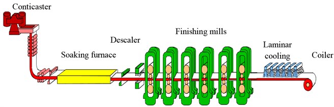
The of the CSP hot strip mills group occurs strong vibration when rolling thin container srip (SPA-H), and will also occur vibration when increasing its load correspondingly. The CSP hot rolling production line has six four-roll finishing mill and the production line layout is shown in Fig. 1. The work rolls of - have large roller diameter (720-800 mm, high chromium cast iron), - are small diameter (540-600 mm, unlimited chilled cast iron). The slab thickness is generally 50-70 mm, the first three mills use large reduction and the reduction rate is up to 50 %.
Fig. 1production line layout of CSP hot strip mill
2. Nonlinear torsional vibration characteristics of mill main drive system
2.1. Nonlinear torsional vibration model of main driving system
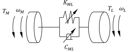
The dynamics model of mill main driving system is established with two inertia and nonlinear damping and nonlinear stiffness under alternating load, which is shown in Fig. 2. The mill rolls are dragged by AC synchronous motor through flexible shaft of the main driving system. It is simplified as two-inertia system. Let , be the inertia moment of the motor and the load respectively. Its rotational speed are and Angle are and respectively. The electromagnetic motor torque is . The load torque is . Shafting torsional damping function is and expressed as a Van der Pol oscillator forms, namely , where is variable coefficient affected by rolling conditions; Shafting torsional stiffness function is denoted by and expressed in the form of duffing oscillators, namely ; is the motor damping coefficient, is the roll (roll gap) damping coefficient.
Fig. 2Nonlinear dynamic model of mill torsional vibration
Its dynamic model can be written as:
and:
where, is the radius of the work roll, is the coefficient of friction between the roll strip (detailed calculation is as Section 2.3), is the rolling force. The rolling force is composed of steady state rolling force and dynamic rolling force, and can be expressed as:
where, is coefficient of rolling power fluctuations, which can be drawn by Section 2.4; is the angular velocity of the rotating roll, is the number of spindle teeth; The calculation of the steady-state rolling force is shown in Section 2.2.
Electromagnetic motor torque is , where, is steady-state value of the motor electromagnetic torque, is the fluctuation coefficient, is the fluctuation frequency.
and are the back and front tension respectively. And there are:
where, and are steady-state value of back and front tension. and are fluctuation coefficient of back and front tension; and are fluctuation frequency of back and front tension and its value can be passed around the mill measured vibration signal.
2.2. Steady rolling force calculation
Applying OROWAN deformation zone equilibrium theory, the hot rolled steady rolling force is calculated as follows:
where, is the strip width, is the horizontal projection length (mm) of the contact arc between flattening rolls and steel strip. Using the Hitchikok elastic flattening equation, we have:
where, is the absolute reduction and ( is roll elastic modulus, is Poisson coefficient).
is impact coefficient of stress state affected by the friction on the arc of contact. And which is calculated as follows by the regression method:
where, , and is the reduction rate, and are strip thickness of entrance and exit.
is the impact factor of the rolling force caused by the back and front tension. Because of the hot strip mill rolling conditions at small tension and the fact that back tension has more influence than front tension, can be calculated as the following simplified formula:
where, and are front and back tension as before. is deformation resistance (Mpa) and its regression formulas of container strip deformation resistance is as follows:
where, strain rate:
and is roll speed, r/min; is rolling temperature.
2.3. Analysis of stand coupling (tension) effect
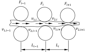
Mills coupled vibration is an important reason for the mill vibration instability. The mills distance and rolling speed and other rolling parameters has an important impact on the stability of the system. According to Hookeps law, the entrance tensile stress is proportional to the integral value of the difference between entrance velocity and exit velocity. The tensile stress of mill are as follows:
where, is Young’s modulus of strip; is the distance between and mill; and are entrance velocity and exit velocity respectively. Relations between the stand are shown in Fig. 3.
Fig. 3Multi-stand relation diagrams
According to the principle of equal mass flow, entrance velocity of rolling is as follows:
where, is the steady state value of exit strip thickness, and are the amplitude and frequency of rolls vertical vibration (all obtained from measured data). And the change of the back tensile stress is as follows:
where, is the distance between the mills. And the rolling force variation caused by can be written as follows:
From Eq. (14), we see that the phase of rolling force change caused by back tension in vibration is ahead the roll vertical vibration displacement of 90°phase angle.
2.4. Characteristics of rolling interface friction
Let us consider lubrication rolling. The interface is full of fluid lubrication and the strip is broadband steel (. Let is contact arc length, be the average thickness of strip entrance and exit). Then, the one-dimensional Reynolds equation can be established as follows for steady and unsteady rolling process:
where is the distance along the rolling direction, is the film thickness, is oil film pressure on the length of the lubricating wedge before the deformation zone entrance, is average of work roll line speed and the strip velocity, is the time, is the dynamic viscosity of the lubricant, and it is not a constant for unsteady hot rolling process, which can be expressed as , where is viscosity at room temperature and atmospheric pressure, θ is the viscosity pressure coefficient, is viscosity temperature coefficient.
From Eq. (15), we see that film pressure variation is composed by the squeeze effects and hydrodynamic effects . In the steady rolling process there are no film thickness fluctuations. Thus, the impact of the former can be ignored and only the latter be considered. Under this condition, the film pressure at any position x can be deduced as follows [9]:
where, is line speed of work roll, is strip velocity, , is roll radius, lubricating layer thickness at the entrance is (where is the bite angle, is yield strength of the strip, is back tensile stress of strip); The film shear stress at an arbitrary position in the deformation zone is as follows [9]:
where, fluid resistance factor is fluid lubrication coefficient is , , is neutral point coordinates, is contact arc length, is pass reduction rate. By the definition of friction factor , and according to the Eqs. (16) and (17), the friction coefficient average of the deformation zone can be approximated as follows [9]:
where, is entry thickness of strip, is the roll diameter. For the convenience of studying, it usually is taken as or polynomial form re-expressed by the Taylor series expansion.
2.5. Spindle unbalanced excitation
The length is about 5 m and the weight is about 7 t of the curved tooth spindles. There are no support; if there exists eccentricity of the inner and outer gear and the imbalance caused by the shaft gravity center offset due to its weight or other factors, then great unbalanced force will appear. This force will damage the dynamic stability. When there is curved tooth headspace, the centrifugal force is as follows:
where, is the weight of the outer tooth sleeve, kg; is the operating speed of couplings, r/min; is relative radial displacement, mm. Due to the centrifugal force, in order to make the inner and outer tooth couplings can automatically make centering, the minimum torque is needed as follows:
where, is the weight of the intermediate shaft or the inner ring gear, kg; is relative eccentricity of inner and outer teeth, mm; is coupling rotational speed, r/min; is tooth pitch diameter, mm. Substituting these parameters into Eq. (20), there is 4.52×10⁷ N∙m, but the measured torque is about 5×10⁵ N∙m, which cannot meet the requirements for automatic centering, that is there must have unbalanced centrifugal force.
2.6. Numerical simulation of torsional vibration mill
The mill structure parameters and process parameters values of the CSP hot strip line are as follows:
4-1
55
The influence of front and back tension (ie, adjacent mill) and strip resistance force on main driving system torsional vibration is simulated emphatically in this paper. The numerical simulation model was set up in Matlab/Simulink using 4-order and 5-order Runge-Kutta method. The influence of rolling material or specification were analyzed by Eq. (5).
The simulation results of the influence of the front and back tension on torsional vibration (main driveline torque) is shown in Fig. 4. We see that mill torsional vibration becomes serious when there is no back tension; the torque mean has increased when there is no front tension. Under these conditions the vibration may increase.
The influence of strip resistance force, ie, different strip materials or specifications, on the main driveline torque is shown in Fig. 5. It can be seen that if rolling containers strip (SPA-H), the torque increases significantly. This is an important factor of torsional vibration start-up.
3. Field experiment analysis
For , and , rolling mill main driving torque was tested using strain measurement and the signal is transmitted by the slip ring; The roll vibration signal was got by piezoelectric accelerometer installed on roller bearing housing; From the site, - produce different vibration levels when rolling container strip (SPA-H, finishing temperature is 900°C) with finishing thickness 1.6 mm. The parameters of the processes and force are shown in Table 1 for , and mill. The working roll diameter is shown in Table 2. The chatter marks obtained by emergency stop sampling of strip and rollers are shown in Fig. 6.
Fig. 4The influence of the front and back tension on torsional vibration
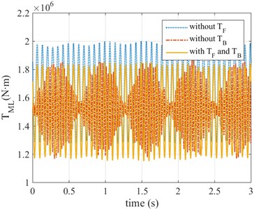
Fig. 5The influence of strip materials or specifications on the main driveline torque
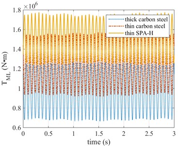
Table 1Rolling processes and force parameters
Entrance width (mm) | 1142.54 | 1142.54 | 1142.54 |
Entrance thickness (mm) | 23.911 | 10.546 | 5.265 |
Entrance temperature (°C) | 991.53 | 971.53 | 951.89 |
Exit temperature (°C) | 993.16 | 972.67 | 954.26 |
Contact arc length (mm) | 74.9 | 46.7 | 26.1 |
Roller temperature (°C) | 37.83 | 38.66 | 39.46 |
Strip hardness (kN) | 46965 | 47298 | 37011 |
Mean rolling force (kN) | 29503 | 25165 | 16080 |
Mean rolling torque (kN·m) | 1663.7 | 861.8 | 296.8 |
Maximum rolling torque (kN·m) | 19171.8 | 11544.2 | 5009.5 |
Rolling power (kW) | 6069 | 6567 | 5241 |
Back tension (N/mm2) | 109.28 | 60.24 | 60.15 |
Rolling velocity (m/s) | 1.45 | 2.87 | 4.81 |
Bending force (kN) | 1400.1 | 1400 | 1099.1 |
Roll axial movement (mm) | -67.87 | -35.01 | -29.42 |
Roll speed (rps) | 0.588 | 0.8 |
Table 2Roll diameters
Upper work roll diameter (mm) | 791.55 | 769.232 | 549.1302 |
Lower work roll diameter (mm) | 791.492 | 769.154 | 549.0517 |
It is found from the strip and roll chatter marks that the strip chatter marks space behind and under the strip surface is 5 cm. The chatter space is 4.67 cm above the strip surface.The chatter marks have same phase, i.e., the under and above are aligned. The frequency of them is about 51 Hz; the space of strip chatter marks behind is 13.89 cm. The phase of the lower part and upper part are inverted.
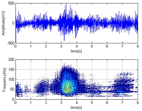
The time domain and time-frequency distribution (Wigner-Ville distribution) of working roll torque is shown in Fig. 7. started biting strip at 3.22 seconds. It can be seen that the work rolls has slight torsional vibration. The dominant frequency is about 17 Hz, torque increased after biting strip. working roll horizontal vibration acceleration is shown in Fig. 8. Its dominant frequency is about 15 Hz.The frequency spectral energy of horizontal vibration is more concentrated than driveline torque, namely main vibration modes is roll horizontal vibration. The roll horizontal acceleration amplitude increases a little after biting strip, and the frequency spectrum diverse slightly.
Fig. 6Strip and roll chatter marks
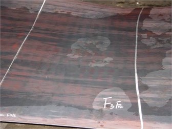
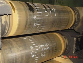
Fig. 7F2 torque time series and Wigner-Ville distribution (F3 biting strip at 3.22 s)
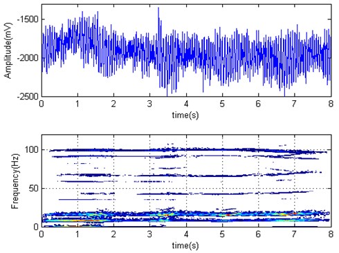
Fig. 8F2 roll horizontal acceleration time series and Wigner-Ville distribution (F3 biting strip at 3.22 s)
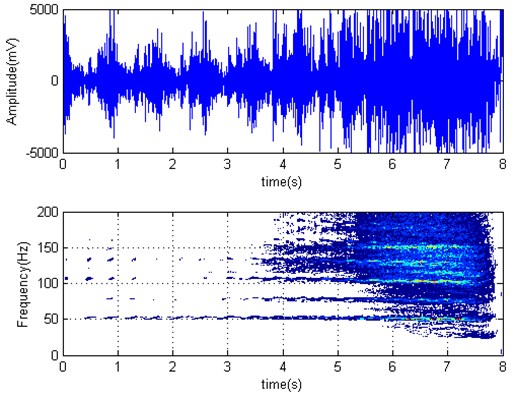
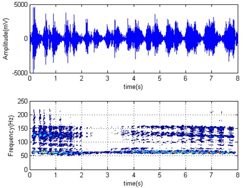
work roll torque time series and Wigner-Ville distribution is shown in Fig. 9. Strip left from at 4.78 seconds. It can be seen that the spectrum is dispersed, the first-order relative advantage frequency is about 20 Hz. torque amplitude increases significantly after strip left from , namely the absence of back tension will worsen the vibration. This coincides with the aforementioned simulation results; work rolls horizontal acceleration time series and Wigner-Ville distribution are shown in Fig. 10. We see that it has “gourd” shape. So there exists obvious vibration. The spectrum has absolute maximum peak at 51 Hz, and coincides with the roll and the strip chatter marks frequencies. horizontal vibration amplitude significantly increases after strip left from . Therefore, that is, the back tension has an important role in suppressing the vibration.
Fig. 9F3 torque time series and Wigner-Ville distribution (strip left from F2 at 4.78 s)
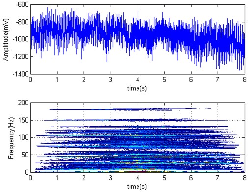
Fig. 10F3 horizontal acceleration time series and Wigner-Ville distribution (strip left from F2 at 4.78 s)
roll torque time series and Wigner-Ville distribution are shown in Fig. 11, and started biting strip at 1.64 seconds, we see that torque amplitude decreased slightly after biting strip and coincided with the aforementioned simulation results. The spectrum is dispersed, that is the front tension has suppression effect on torsional vibration. The work roll horizontal acceleration time series and Wigner-Ville distribution are shown in Fig. 12. We can see that acceleration amplitude has been reduced after biting strip, that is the front tension has suppression effect on horizontal vibration and dominant frequency has no obvious change.
Fig. 11F3 roll torque time series and Wigner-Ville distribution (F4 started biting strip at 1.64 s)
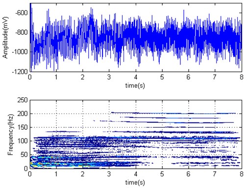
Fig. 12F3 roll horizontal acceleration time series and Wigner-Ville distribution (F4 started biting at 1.64 s)
4. Conclusions
1) The two degrees of freedom mill drive system nonlinear torsional vibration model with nonlinear stiffness and nonlinear friction damping was established. The calculation method and its effect on the torsional vibration system of the rolling force, multi-stand coupling (tension), the interfacial friction characteristics and spindle unbalanced incentives and other factors are discussesd in this paper.
2) By the numerical simulation results analysis of the model, it is shown that the front and back tension have suppression effect on mill vibration. When there is no back tension, the mill torsional vibration is obvious. At the same time rolling resistance force is an important factor responsible for mill torsional vibration.
3) Based on long-term tracking test and signals time-frequency analysis, the experimental results show that the tension plays a very good role on mill vibration suppression.
References
-
Bar A., Bar O. Types of mid-frequency vibrations appearing during the rolling mill operation. Journal of Materials Processing Technology, Vol. 162-163, Issue 5, 2005, p. 461-464.
-
Zheng Yongjiang, Xie Zhaohui, Li Yigeng, Shen Guangxian Spatial vibration of rolling mills. Journal of Materials Processing Technology, Vol. 213, Issue 4, 2013, p. 581-588.
-
Bar Adam, Świątoniowski Andrzej Interdependence between the rolling speed and non-linear vibrations of the mill system. Journal of Materials Processing Technology, Vol. 155-156, Issue 11, 2004, p. 2116-2121.
-
Hu Pei-Hua, Ehmann Kornel F. Regenerative effect in rolling chatter. Journal of Manufacturing Processes, Vol. 3, Issue 2, 2001, p. 82-93.
-
Wu Y. X., Duan J. A. Frequency modulation of high-speed mill chatter. Journal of Materials Processing Technology, Vol. 129, Issue 1-3, 2002, p. 148-151.
-
Panjković Vladimir, Gloss Ronald, Steward John, Dilks Stephen, Steward Robert Causes of chatter in a hot strip mill: observations, qualitative analyses and mathematical modelling. Journal of Materials Processing Technology, Vol. 212, Issue 4, 2012, p. 954-961.
-
Wang Lipo, Frayman Yakov A dynamically generated fuzzy neural network and its application to torsional vibration control of tandem cold rolling mill spindles. Engineering Applications of Artificial Intelligence, Vol. 15, Issue 6, 2002, p. 541-550.
-
Furumoto Hideaki, Kanemori Shinya, Hayashi Kanji, Sako Akira Enhancing technologies of stabilization of mill vibration by mill stabilizing device in hot rolling. Procedia Engineering, Vol. 81, 2014, p. 102-107.
-
Xiaobin Fan Vibration Problem Research for CSP Mill Stand. University of Science and Technology Beijing, Beijing, 2007.
About this article

