Abstract
An analytical method is provided for ground motion of a semi-cylindrical hill with a subsurface linear crack under SH -wave. A suitable Green’s function for the problem discussed in this paper is constructed by complex function and multi-polar coordinate systems. It is the fundamental solution of the displacement field for an elastic half space with a semi-cylindrical hill under an out-plane harmonic line source which is loading at an arbitrary point in the basal body. According to the displacement field solution of scattering of SH wave by a semi-cylindrical hill, the Green’s function of this paper is used to construct a subsurface linear crack. With the boundary condition, a series of infinite algebraic for the problem can be set up. And the displacement field of a semi-cylindrical hill with a subsurface linear crack impacted by SH wave is expressed. The numerical example shows the influence of wave numbers, the length of crack, the incident angle and the ratio of hill on the hill’s displacement.
1. Introduction
It is an important subject in earthquake engineering to study the influence of irregular topography on the ground motion and provide the reasonable parameters for the seismic design [1-5]. In the nature, because of the difference of geological structure, the geological defects such as the cracks and inclusions are often found near the irregular topography. Therefore, the researches on the influence of the geological defects in basal body on the irregular topography have an important significance in both theory and practice of engineering. Liu and Wang present the solution of the scattering of SH-wave by a semi-cylindrical hill above a subsurface cavity in 2006 [6]. And then, the ground motion of multiple semi-cylindrical hills above a subsurface elastic cylindrical inclusion under SH-wave is solved by Lv [7]. For the subject of scattering of elastic waves by the crack, there are a number of publications, but most of them are concerned with the problems that scattering of waves by the interface cracks or the defects containing in the cracks [8-13]. In 2006, Yang and other researchers presented the solution of dynamics of a mode III crack impacted by elastic wave in half space with a removable rigid cylindrical inclusion [14]. By using of Green’s function, Liu investigated the scattering of SH wave by a semi-cylindrical canyon and a crack in 2007 [15]. Compared with the case of canyon, it is more difficult to research the scattering of SH wave by a semi-cylindrical hill and a crack. Although the numerical methods can solve this kind of complex problems, people are still trying to find an analytical solution to reveal the fundamental law and characteristics of interaction of irregular topography, inclusions and cracks. Obviously, the study on which will provide a more comprehensive theoretical support for the theoretical research on topography.
This paper presents a mathematical model and a method of solution for the response of a semi-cylindrical hill above a subsurface linear crack to incident SH wave by the Green’s function and the complex variable function. The idea of using Green’s function to study the crack comes from [9-15]. Firstly, assuming that the crack does not exist, in the basal body of half space with a semi-cylindrical hill, the stress of an arbitrary point () can be solved [6]; then the stress which has the same magnitude as but in the opposite direction is applied to the same point, the total stresses of this point is zero, namely, the point is broken. If the stress of each point in a linear region is zero, the linear region can be considered as a linear crack. Therefore, the Green’s function in this paper is the solution of displacement field for an elastic half space with a semi-cylindrical hill under an out-plane harmonic line source loading at an arbitrary point in the basal body. In references [9-14], the Green’s functions are the fundamental solutions of the displacement fields for an elastic whole space (or half space) with a hole (or a cavity, an inclusion) impacted by an out-plane harmonic line source loading at the interface (or horizontal surface). While in reference [15], the Green’s function is the fundamental solution of the displacement field for a half space with a semi-cylindrical canyon under an out-plane harmonic line source loading at an arbitrary point in the matrix. Compared with reference [9-15], it is more difficult to solve the Green’s function in this paper due to the existence of the hill. Obviously, the study on which will provide a more comprehensive support for the theoretical research on topography.
As shown in Fig. 1, the whole solution model is divided into two parts [6]. If an out-plane harmonic line source loading is applied to an arbitrary point in the basal body, the disturbance impacted by the line source loading can be considered as the incident wave, and the corresponding scattered wave fields are generated in two parts respectively. According to the boundary conditions of these two parts, the Green’s function discussed in this paper can be obtained, which is the solution of displacement field for an elastic half space with a semi-cylindrical hill under an out-plane harmonic line source loading at an arbitrary point in the basal body. In a similar way, under the SH wave, the stress of each point in the matrix can be solved, which is the stress result of scattering of SH wave by the semi-cylindrical hill. Then, the anti-plane force (which has the same magnitude as of each point but in the opposite direction) is loaded on each point of the linear region where the crack will happen, therefore, the total stresses along the linear region are zero, and the crack is constructed.
2. Model
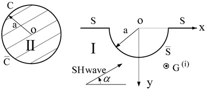
The 2D model consists of a semi-cylindrical hill and a subsurface crack in an elastic half-space is shown in Fig. 1. All the media are linear, elastic, homogeneous and isotropic. Fig. 2 shows the division of the model under an anti-plane harmonic linear source loading. Domain I consists of boundary and ; domain II is a circular domain, including the boundary and . Obviously, and are the common boundary of two parts, which means the displacements and stresses at the common boundary should be continual.
Fig. 1The model of a semi-cylindrical hill above a subsurface linear crack
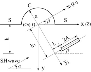
Fig. 2The division of the solution domain
3. Green’s function
3.1. Governing equation
The Green’s function discussed in this paper is the fundamental displacement solution for an elastic half space which contains a semi-cylindrical hill impacted by an anti-plane harmonic linear source loading at any point in domain I. The relationship between the Green’s function and time factor is (and will be omitted). In complex plane , the displacementfunction satisfies the governing equation:
where , is the circular frequency of ; is the shear wave velocity of the medium; and are mass density and shear modulus of medium respectively.
In the polar coordinate system, the corresponding stresses can be written as:
3.2. Derivation of Green’s function
3.2.1. Incident wave, reflected wave and scattered wave in domain I
As shown in Fig. 2, in the whole elastic space, the disturbance impacted by the anti-plane line source loading will be considered as the incident wave and expressed as follows:
In complex plane , the Eq. (3) will be written as:
Because of the horizontal boundary, a reflected wave is constructed, and the sum of and should satisfy the stress free at the horizontal boundary. In complex plane , takes the form:
The stresses due to and will be expressed as:
In domain I, the scattered wave from the canyon is constructed to satisfy the stress free at horizontal surface , takes the form:
where are unknown coefficients.
The corresponding stress is:
3.2.2. Standing wave in domain II
As shown in Fig. 2, the anti-plane line source loading in domain I can be considered as the incident wave , so there will be a standing wave in domain II, which should satisfy the conditions that stress free at the hill edge and arbitrary at other point, and the conditions can be expressed as:
where are unknown coefficients
In domain II, the standing wave function corresponds to the Eq. (2) and satisfies the motion equation takes the form:
where are arbitrary constants; from Eq. (11), the stress as follows:
Expanding Eq. (10) by Fourier series in region :
In which:
Comparing Eq. (12) with Eq. (13) at :
Substituting Eq. (15) into Eq. (11), a standing wave function will be obtained:
The stress from Eq. (16) is:
In domain II, Eq. (16) is the constructed standing wave which satisfies stress free at boundary and arbitrary at boundary and subject to Eq. (1) under the line source loading.
3.2.3. Boundary conditions and derivation of Green’s function
In complex plane , domain I and domain II are assembled together, which means that the displacements and stresses at the common boundary should be continual. The conditions are:
Substituting the expressions of displacements and stresses (Eq. (4)-Eq. (9), Eq. (16)-Eq. (17)) into Eq. (18), and multiplying both sides of it by and integrating over the interval , a series of infinite algebraic equations for solving the unknown coefficients , will be obtained.
So the special Green’s function discussed in this paper can be given by:
4. Scattering of SH-wave by a semi-cylindrical hill above a subsurface crack
4.1. Scattering of SH-wave by a semi- cylindrical hill
To study the motion of semi-cylindrical hill to incident SH-wave, as shown in Fig. 2, the solution domain is divided into two parts. In circular domain II, the disturbance impacted by SH wave will be represented as a standing wave, which satisfies the conditions that stress free at the edge of the hill and arbitrary at other part. Such standing wave can be obtained by the same way as Eq. (16) [6]:
The stresses due to Eq. (20) are:
where takes the same form with Eq. (14).
In complex plane , incident wave and reflected wave will be given:
The stresses due to and will be expressed as:
The scattered wave from the semi-cylindrical canyon takes the form as Eq. (28), which satisfies the stress free condition on the horizontal surface:
where are unknown coefficients, and the corresponding stresses are given by:
At the contact boundary (), the displacements and stresses should be continual, namely:
Substituting the expressions of displacements (Eq. (20), Eqs. (23)-(24), Eq. (29)) and stresses (Eq. (21), Eqs. (25)-(26), Eq. (30)) into Eq. (31), and multiplying both sides of it by and integrating over the interval , a series infinite algebraic equations solving the unknown coefficients , will be obtained.
Under SH wave, the displacement and stress field in these two domains can be expressed respectively as:
4.2. Displacement functions with the crack
The displacement and stress field for scattering of SH wave by the semi-cylindrical hill has been solved (Eq. (33)-(34)), that is the stress of an arbitrary point in domain I is known. Then a linear crack with arbitrary position and direction can be constructed in domain I by “cut”. That is to say, under the SH-wave, the stress of an arbitrary point in domain I is . If a force equal and opposite with is applied to the same point, the total stress of the point is zero. Such forces are applied to each point of the region where the crack will happen, therefore the total stress of this region is zero, and the region can be thought as a crack, as shown in Fig. 3.
By using of the constructed special Green’s function (Eq. (19), the final displacement fields with the coexistence of semi-cylindrical hill and crack in two domains respectively will be obtained as follows:
Fig. 3Model of constructed linear crack
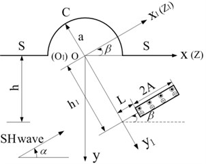
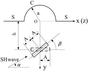
Fig. 4The solving model
5. Results and analysis
The results presented in terms of the following dimensionless parameters:
: The dimensionless wave number, can be expressed by the wave length :
and can be written as:
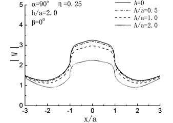
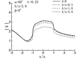
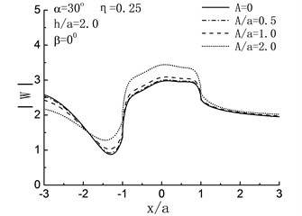
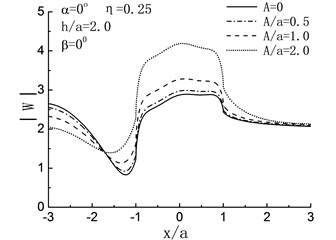
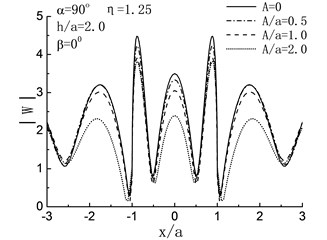
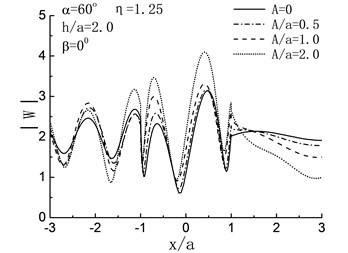
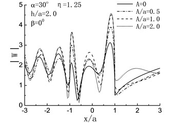
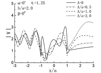
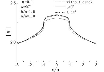
The presented results are calculated based on the model shown in Fig. 4: the excitation is a plane SH-wave with angle of incidence ; the length and the buried depth of linear crack are and ; the hill with radius , is the angle between linear crack and axis; represents the hill’s boundary and is the horizontal surface. Fig. 5 to Fig. 8 show the influence of , and on displacement amplitudes of the points on and impacted by SH-wave with different and . represent the intersections of the hill‘s boundary and horizontal surface , while and represent the points on and .
Fig. 5 illustrates the variation of surface displacement amplitudes with different , and when 2.0 and 0°. For the case of , namely, the length of crack is zero, the solving model shown in Fig. 4 can be considered as a semi-cylindrical hill in half space and the crack does not exist, as shown in Fig. 5, when , the variation of surface displacement amplitudes is identical to the results in the reference [6].
Fig. 5Variation of surface displacement amplitudes with x/a when β= 0°
a)
b)
c)
d)
e)
f)
g)
h)
When , the influences of the length of crack on the surface displacement amplitudes of the hill depend on incident angle largely. For 90°, 60°, as shown in Fig. 5(a), (b), the displacement amplitudes of the hill decreased with increasing of the length of crack. Take the case of 90°, 2.0, 1.0 and 0.5 for example, compared with the case of , there are respectively 30 %, 9 % and 3 % decreases in the displacement amplitudes of the hill peak. While with the reduced , the result is contrary. As shown in Fig. 5(c), (d), increased with the increasing of . For 0°, compared with the case of , the displacement amplitudes of the hill peak increased by 45 %, 15 % and 4 % when 2.0, 1.0 and 0.5. For high frequency , dynamic characteristics are exhibited, and the fluctuation of the displacement amplitudes can be seen in Fig. 5(e) to (h).
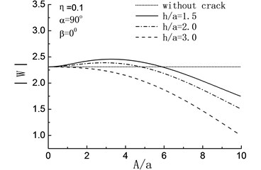
In Fig. 6, the response spectrum of the amplitude at the peak point of the hill are shown with different when 90° and 0°. For , compared with without the crack, except for the embedded depth of the crack is , the existence of crack has different amplification effects on the displacement amplitude of the hill peak when and in the rang of and respectively.
When , there is a constant decrease in the amplitude at the peak point of the hill with the increase of , and the amplitudes are smaller than those in the crack-absence case, which means that the presence of the crack has some earthquake damping function.
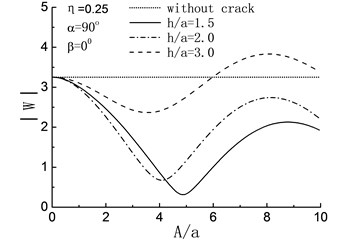
When , the amplitudes at the peak point of the hill show fluctuating changes with the increase of when and , and always less than that of crack-absence case. For the deeper embedded depth of the crack, take the case of for example, the crack has some amplification effects to the displacement amplitude of the hill peak within the range .
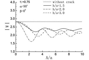
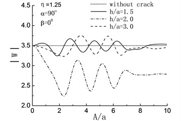
When , the existence of crack has a energy absorbing effect on in all three different embedded depth. While for , when and , manifest themselves as a curve with periodic change, and the curve flattens out gradually towards and a whisker away from the case of without crack. When , the curve of still shows the periodic change and the amplitudes are smaller than those in the crack-absence case.
Fig. 6Variation of displacement amplitudes of the hill peak with the length of the crack when β= 0°
a)
b)
c)
d)
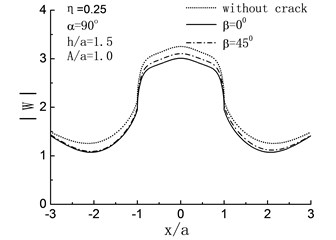
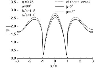
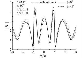
Fig. 7 illustrates the influence of on the surface displacement amplitudes of the half space when 90°, and . It will be seen that except for , the displacement amplitudes of the hill surface will decrease because of the crack. For high-frequency band 0.75, 1.25, compared with the horizontal crack 0°, the oblique crack 45° has obvious decreasing effect on the displacement amplitudes of the hill surface. As for , compared with the just one hill case, the displacement amplitudes of the hill peak have 15 % and 4 % decreases when 45° and 0° respectively. At the same time, the displacement amplitudes decrease on the left side of the hill ( –1.0) and increase on the right side due to the existence of oblique crack 45°.
Fig. 7Variation of surface displacement amplitudes with different direction of crack when α= 90°
a)
b)
c)
d)
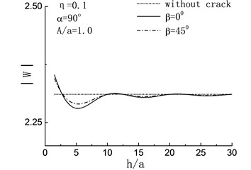
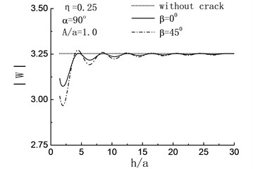
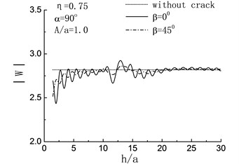
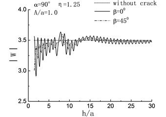
Fig. 8Variation of displacement amplitudes of the hill peak with the length of the crack when β= 0°
a)
b)
c)
d)
In Fig. 8(a) to (d), the displacement amplitude of the hill peak are compared with the variation of embedded depth of crack when . For , namely the quasi-static case, the magnifying effects of the crack to the can be seen in both the case of 45° and 0° when . While in the range , the displacement amplitude of the hill peak shows periodical change and the values of them always less than those of crack-absence case, which means that the presence of the crack has some earthquake damping function under certain condition. When , the effect of the crack can be ignored. For , both of the horizontal crack and the oblique crack show remarkable damping action. And in the range of and , the damping actions caused by the oblique crack 45° are more obvious than those by the horizontal crack 0°.
For the high frequency 0.75, 1.25, the periodical changes still can be seen in the varying curve of the displacement amplitudes of the hill peak , while with the increase of , the amplitudes increase and the vibration become severe, namely the variation of the curve display the dynamic characteristics gradually. Moreover, when 45°, the amplitudes of curve are obvious less than the case of 0°. In particular, for 0.75 and 1.25, amplitude increase can be seen in the range and respectively.
6. Conclusions
1) The displacement amplitudes of the hill peak show the periodical decrease with the increase of . When , the influence of crack tends to stabilization and can be ignored.
2) Obviously that the subsurface crack has no effect on the displacement amplitudes of the hill surface. Under the vertical incident SH wave, both of the horizontal and the oblique crack illustrate some damping effects on the displacement amplitudes of the hill peak, and the damping actions caused by the oblique crack are more obvious than those by the horizontal crack.
3) The analysis method presented in this paper is just used to the case that the crack outside of the domain II. In the dividing of solution domain, when the common boundary and the crack contact or intersect with each other, a special analysis will be applied.
References
-
Trifunac M. D. Scattering of Plane SH-waves by a semi-cylindrical canyon. Earthquake Engineering and Structure Dynamics, Vol. 2, 1973, p. 267-281.
-
Yuan X. M., Men F. L. Scattering of plane SH-waves by a semi-cylindrical hill. Earthquake Engineering and Structure Dynamics, Vol. 21, 1992, p. 1091-1098.
-
Liang J. W., Luo H., Lee V. W. Diffraction of plane SH waves by a semi-circular cavity in half-space. Earthquake Science, Vol. 23, Issue 1, 2010, p. 5-12.
-
Wang G. Q., Liu D. K. Scattering of SH-wave by multiple circular cavities in half space. Earthquake Engineering and Engineering Vibration, Vol. 1, Issue 1, 2002, p. 36-44.
-
Qiu F. Q., Liu D. K. Antiplane response of isosceles triangular hill to incident SH waves. Earthquake Engineering and Engineering Vibration, Vol. 4, Issue 1, 2005, p. 37-46.
-
Liu D. K., Wang G. Q. Antiplane SH-deformation of a semi-cylindrical hill above a subsurface cavity. Acta Mechanica Sinica, Vol. 38, Issue 2, 2006, p. 209-218, (in Chinese).
-
Lv X. T. Scattering of SH-wave by multiple semi-cylindrical hills above a subsurface elastic cylindrical inclusion. Journal of Vibroengineering, Vol. 16, Issue 6, 2014, p. 2695-2701.
-
Shi G. C. Stress distribution near internal crack tips for longitudinal shear problems. Journal of Applied Mechanics, Vol. 32, Issue 1, 1965, p. 51-58.
-
Liu D. K., Liu H. W. Scattering of SH wave by cracks originating at a circular hole edge and dynamic stress intensity factor. Acta Mechanica Sinica, Vol. 31, Issue 3, 1999, p. 292-299, (in Chinese).
-
Shi S. X., LiuD. K., Yang Q. S. Dynamic stress concentration and scattering of SH wave lining with crack and its interaction. Explosion and Shock Waves, Vol. 20, Issue 3, 2000, p. 228-234.
-
Liu D. K., Chen Z. G. Scattering of SH-wave by cracks originating at an elliptic hole and dynamic stress intensity factor. Applied Mathematics and Mechanics, Vol. 25, Issue 9, 2004, p. 958-966.
-
Liu D. K., Lin H. Scattering of SH-waves by an interface linear crack and a circular cavity near biomaterial interface. Acta Mechanica Sinica, Vol. 20, Issue 3, 2004, p. 317-326.
-
Yang Z. L., Liu D. K., Lv X. T. Dynamics of a mode III crack impacted by elastic wave in half space with a removable rigid cylindrical inclusion. Key Engineering Materials, Vols. 324-325, 2006, p. 679-682.
-
Qi H., Yang J. Dynamic analysisfor circular inclusions of arbitrary positions near interfacial crack impacted by SH-wave inhalf-space. European Journal of Mechanics – A/Solid, Vol. 36, 2012, p. 18-24.
-
Liu G., Li H. L., Liu D. K. Scattering of a semi-cylindrical canyon and a crack with incident SH waves. Explosion and Shock Waves, Vol. 27, Issue 2, 2007, p. 171-178, (in Chinese).
About this article

