Abstract
Shunt injection serves an important role in the labyrinth seal static and rotordynamic characteristics which are important in the prediction of turbomachinery stability. This paper analyzed how the shunt injection affects the seal rotordynamic characteristics, and presented an improved impedance method based on unbalanced synchronous excitation to identify the rotordynamic coefficients of labyrinth seals on a rotor test rig. The influences of the rotational speed and the inlet/outlet pressure ratio on the rotordynamic characteristics of shunt injection seals with and without shunt injection were identified and analyzed. The experimental results reveal that all the seal rotordynamic coefficients increase with the rotational speed, and the inlet/outlet pressure ratio. The shunt injection contributes to decreasing the seal cross-coupled stiffness, and increasing the direct damping. The shunt injection plays an important role in decreasing the effective stiffness coefficient, and increasing the effective damping coefficient. The shunt injection can effectively improve the rotor stability. The experimental results lay the foundation for designing the annular seals with shunt injection.
1. Introduction
Seals are widely used in compressors and turbines to restrict leakage between different pressure regions. They have been confirmed as a major source of destabilizing forces resulting in rotordynamic instability problems [1-3]. Extensive experimental investigations and field troubleshooting experience have confirmed the cross-coupled stiffness coefficients generated by gas preswirl velocity at the labyrinth seal entrance to be the major mechanism of inducing a load-dependent instability vibration [4-6].
A part of gas following along the shaft may motion circumferentially, which is called as a swirl. Labyrinth seals with strong gas swirl on the direction of shaft generate a destabilizing force, which is primarily influenced by the velocity of swirl at the entrance of labyrinth seal. In practice, shunt injection and swirl brake are two promising techniques to enhance rotor stability if the predicted log-decrement is relatively low [7-9].
Researchers show that the swirl brakes at the seal entrance play an important role in increasing rotordynamic stability [10-12], even though some cases are known in which have not produced a satisfactory effect. Under the condition that the seal inlet/outlet pressure difference is large or that the seal axial length is long, the swirl brakes have few impacts on improving the seal stability [13].
An alternative solution is to be found in the use of the shunt injection [14-17]. The shunt injection is mainly applied to the balance piston seal. The balance piston is located after the last stage of the impeller and is longer than that of the nech ring seal or the interstage seal. The basic idea of shunt injection is to reduce or eliminate the swirl effect by eliminating the swirl velocity near the high pressure end of the seal by injecting a jet flow toward the rotor. Sung-young [18] presented the first shunt injection seal rotordynamic coefficient results obtained by a CFD approach. Soto and Childs [19] studied the rotordynamic characteristics of the labyrinth seal with shunt injection via experimental approach. The results show that labyrinth seals with injection against rotation are better able to control rotordynamic instabilities than ones with radial injection. N. Kim [20] predicted the effects of shunt injection on the rotordynamics of gas labyrinth seals by a CFD perturbation model. The prediction shows the primary advantage of the shunt injection is drastically reducing the cross-coupled stiffness. Although the shunt injection is widely implemented, few experiments are adopted to investigate the effect of different quantities and sizes of shunt injection on the static and rotordynamic characteristics of labyrinth seals.
In this paper, the effectiveness of the shunt injection was experimentally investigated used the labyrinth seals on a rotating test rig. An improved impedance method based on unbalanced synchronous excitation method was used to investigate the rotordynamic coefficients of seals. To study the effects of the shunt injection on the seals, four different shunt hole densities and diameters for the following conditions: (1) without shunt injection, (2) with shunt injection (Ø6×12), (3) with shunt injection (Ø6×14), (4) with shunt injection (Ø8×12). The influences of several system parameters, such as shunt densities, injection diameters and the operating conditions (inlet/outlet pressure ratio and rotating speed) were measured and discussed, respectively.
Fig. 1Schematic diagram of the seal test rig
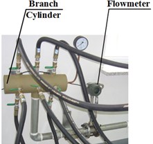
a) Branch cylinder
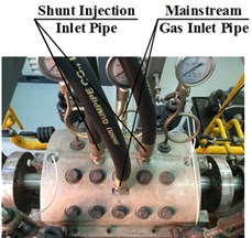
b) Cylinder
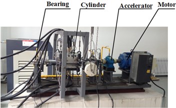
c) Seal test rig
2. Test-rig description
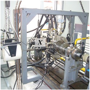
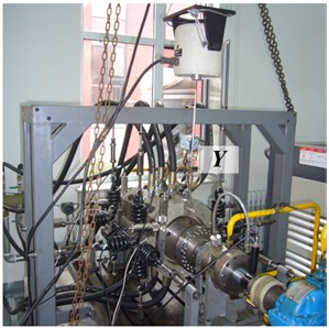
The rotordynamic test rig adopted in this study is shown in Fig. 1. A slender steel shaft is supported by two steel oil bearings lubricated by ISO VG32 turbine oil. The middle of the shaft holds a steel sleeve with labyrinth seals and the diameter 180 mm. Near the bearings, two steel balance disks are used to regulate the original rotor vibration and to provide unbalanced exciting forces. The magnitudes and angles of unbalanced excitation forces can be changed through adjusting the location of unbalance blocks fixed on the balance disks. Two rings of copper labyrinth seals are fixed on the interior wall of the cylinder. The cylinder is hung by springs (exchanged to adjust stiffness) on vertical and horizontal directions. The cylinder is easily excited by seal force which is approximately the same frequency as the rotor rotation. At the free end of shaft, 15 kW DC motor drives the shaft through speed-increasing gearbox. The rotor speed can be adjusted from 500 rpm to 6 000 rpm. To obtain the impedance function of cylinder, an electromagnetic shaker is to apply dynamic load make the cylinder with loads up to 500 N. The dynamic load applied to the cylinder is measured with the load cell located between the stinger and shaker frame. In order to study the rotordynamic characteristics, the test rig is equipped with a branch cylinder, which sets 8 high pressure gas transmission pipes. The four seal mainstream gas inlet pipes and the four shunt injection gas pipes are all equally spaced on the circumference. High pressure appendix transfers different pressure gas to the seal entrance and shunt holes through the surge valve. The inlet pipes and placement of test seals are shown in Fig. 2.
Fig. 2The seal installation type
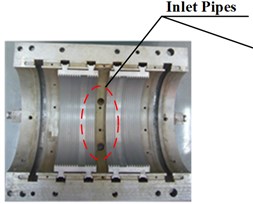
a) Seal without shunt holes
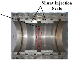
b) Seal with shunt holes
As illustrated in Fig. 3 and Fig. 4, 4 velocity sensors and 4 proximitors are used to measure the vibrations of cylinder and rotor. A key phase transducer is to measure rotating speed and its phase. The phase of all vibration signals are obtained from this keyphasor signal. All measurements are conducted under 25 °C room temperature.
Fig. 3Photo of sensor placement
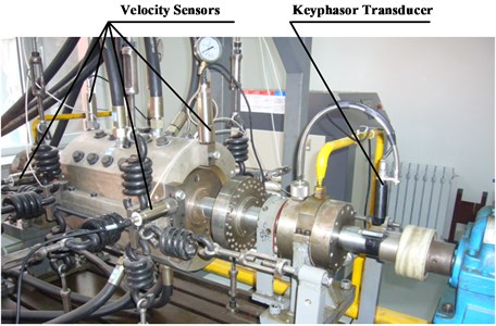
Table 1Seal dimensions and operating conditions
Physical properties | Value |
Rotor diameter (mm) | 180 |
Shunt hole angle (deg) (from radial) | 15 |
Radial interference between rotor and seal (mm) | 0.2 |
Shunt hole diameter (mm)×quantity | Ø6×12, Ø6×14, Ø8×12 |
Number of seal teeth | 15 |
Number of air inlet pipes (cylinder) | 8 |
Fluid | compressed air |
Pressure downstream (MPa) (discharge) | 0.1 |
Pressure upstream (MPa) (supply) | 0.5-0.7 |
5-7 | |
Shunt injection pressure (MPa) | 0.8 |
Rotor speed (rpm) | 1500-3000 |
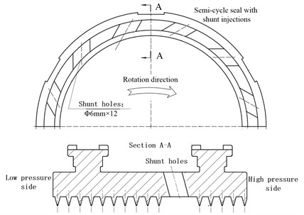
Table 1 and Fig. 5 show the details of the test seal dimensions and operating conditions for measurements of seal force coefficients. The selected geometry is representative of a medium pressure centrifugal compressor balance piston seal, more specifically the labyrinth seal is a straight through seal with 15 statoric teeth facing a smooth rotor.
Fig. 4Schematic diagram of measurement system
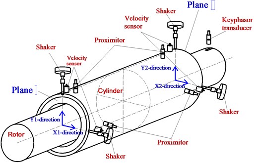
Fig. 5Dimensions of test seal
3. Identification methodology
The proceeding section introduced the test apparatus and facility, and explained the dynamic measurements taken at the seals. The present section explains how the measurements are used to identify the rotordynamic coefficients.
3.1. Equivalent air force identification
In order to calculate the resultant forces exerting on the ends of the cylinder, a kinematical model of the cylinder was established. When the cylinder was excited on the middle of plane and tilting motion exists, the displacements of the two ends of planes varied with amplitude and phase. Considering this situation, this paper built a fluid-force identification method with 4 degrees of freedom for the cylinder system. As shown in Fig. 10, -direction is taken as the object of study. Under the action of seal force and elastic force, the kinematic equation is presented as:
where is the equivalent seal force of plane I, the equivalent seal force of plane II, the cylinder displacement, the deflection angle, and (1, 2) the stiffness and damping coefficients of the supporting springs, respectively. From Fig. 10, and can be denoted by:
Eq. (1) is rewritten as:
Under the external harmonic excitation with frequency, assuming:
When Eq. (4) is inputting into Eq. (3), there is:
where, (1, 2, 3, 4) is the impedance function of the test cylinder, which are expressed as:
Eq. (6) indicates that , decided by the inherent characteristics of the system, is the function of the excitation frequency . Thus, is obtained by external excitation experiments in the -direction of the two selected planes.
By considering the coupling effect between the vertical and horizontal directions, Eq. (5) can be expanded as:
where:
is the equivalent seal force, the displacement vector of cylinder vibration under different inlet pressures and speeds. To acquire the matrix , the cylinder assembly is excited by a shaker at two ends of planes from two orthogonal directions (, ) on each plane, shaker excitation experiment is shown in Fig. 7.
Fig. 6Schematic diagram of seal-force identification model
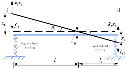
Fig. 7Shaker excitation experiment
a) Shaker excited in direction
b) Shaker excited in direction
To eliminate the influence of cylinder tilting motion, the total seal forces acting on the cylinder is calculated on the and directions as follows:
If the impedance matrix and the cylinder vibration under different working conditions are measured, the equivalent seal force can be calculated by Eq. (8).
3.2. Rotordynamic coefficients identification
The general governing equation of film forces on seals, which have oscillations relative to the rotor, is given by the linearized force-displacement model:
where and are the fluid-film reaction forces on seals on the and directions; , , and the stiffness, damping, and added-mass coefficients, respectively; the subscripts and represent the direct terms; the subscripts and represent the cross-coupled terms. These coefficients vary with the equilibrium position of the rotor, rotating speed, inlet/outlet pressure ratio, temperature conditions, and so forth. The off-diagonal coefficients in Eq. (9) are caused by fluid rotation, which can be applied to liquid annular seals. However, for the air annular seals, the added-mass terms are negligible. Thus, for air seals, Eq. (9) determined in the frequency domain derives from:
where, is the coefficients defined in Eq. (10) by where the frequency of excitation force from fluid force, which is the same frequency as the rotor rotation; and the relative displacements between the cylinder and rotor on horizontal and vertical directions. To avoid the tilting motion in the cylinder, and are gained by
where, , , and are the complex variables, and the relative displacement of plane I on orthogonal directions, and the relative displacement of plane II.
Eq. (10) provides two equations with the four unknowns (, , , and ). To provide four independent equations, the number and installation angle of balance mass fixed on balance disks were changed to generate different magnitudes and directions of exciting forces with synchronous frequency. The equations are:
where the subscripts I and II represent two different unbalance conditions.
When the absolute displacements in the two ends of the cylinder and the relative displacements between the cylinder and rotor are determined, can be calculated by Eq. (12). Since , the real part of can be used to calculate direct and cross-coupled stiffness while the imaginary part can be adopted to estimate the coefficients of direct and cross-coupled damping.
4. Test conditions and procedure
Fig. 8 shows shunt injection applied to a balance piston seal for a centrifugal-compressor. As shown in Fig. 8, shunt holes are equally arranged on the stator wall on the circumference and are usually very close to the high-pressure section. In this paper, the effectiveness of the shunt injection was experimentally investigated when used with the labyrinth seals on a rotating test rig. An improved impedance method based on unbalanced synchronous excitation method was used to investigate the rotordynamic coefficients of seals. To study the effects of the shunt injection on the seals, four different shunt hole densities and diameters for the following conditions: (1) without shunt injection, (2) with shunt injection (Ø6×12), (3) with shunt injection (Ø6×14), (4) with shunt injection (Ø8×12). The operating conditions ( and rotating speed) are accounted for. All of the seals have the same nominal diameter, effective length and clearance in order to have a straightforward comparison.
Fig. 8The physical map of seal with shunt holes (Ø6×12)
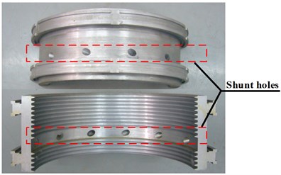
Fig. 9Rotordynamic coefficients versus rotating speed (Pr= 7)
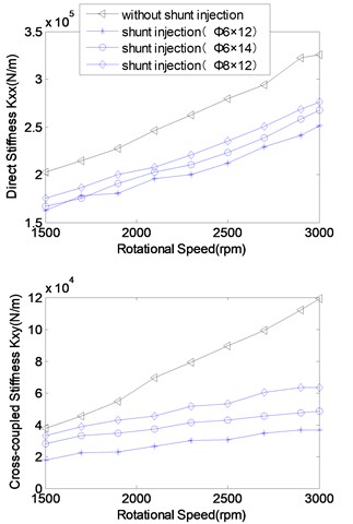
a) Stiffness coefficients
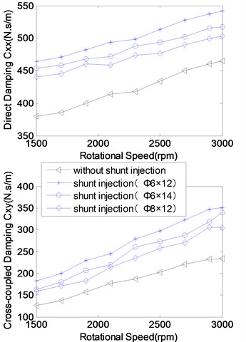
b) Damping coefficients
5. Rotordynamic coefficient results
5.1. Influence of rotating speed on the rotordynamic coefficients
Fig. 9 shows the experimental analysis for the effect of rotating speed on rotordynamic coefficients. The experiments were carried out at a of 7, and rotating speeds of 1500-3000 rpm.
In Fig. 9, it is revealed that (1) rotating speed significantly influences stiffness and damping coefficients; (2) the rotordynamic coefficients are shown to increase with rotating speed due to the positive swirl induced by rotation; (3) shunt injection is promising to effectively reduce the cross-coupled stiffness coefficients and increase the direct damping coefficients. For instance, the seal with shunt injection (Ø6×14) suffices to reduce 25 %-75 % the coefficients of cross-coupled stiffness and the seal with shunt injection (Ø6×12) further potentially reduces that.
5.2. Influence of inlet/outlet pressure ratio on the rotordynamic coefficients
Through the experimental analysis for the rotordynamic coefficients with increasing inlet/outlet pressure ratios at 3000 rpm, and of 5-7, the results are demonstrated in Fig. 10.
As is shown in the Fig. 10, (1) the stiffness and damping coefficients almost linearly increase with the inlet/outlet pressure ratio; (2) shunt injection is conductive to effectively reduce cross-coupled stiffness and increase the direct damping; (3) the greater the shunt injection velocity is, the more effectively shunt injection works on the seal cross-coupled stiffness and direct damping coefficients. The cause of the results above is that the destabilizing forces from the labyrinth seals acting on the rotor become larger with the increase of the inlet swirl into the labyrinths as the leakage increases. The shunt injection does have a major positive contribution to reducing the seal circumferential pressure difference, the seal destabilizing forces.
Fig. 10Rotordynamic coefficients versus inlet/outlet pressure (rotational speed: 3000 rpm)
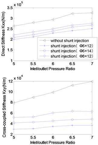
a) Stiffness coefficients
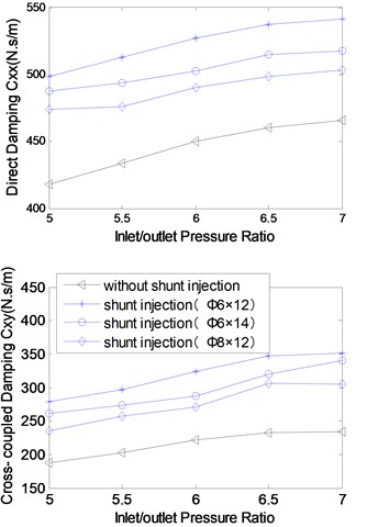
b) Damping coefficients
5.3. Analysis of seal stability
Effective stiffness and effective damping coefficients are the comprehensive index of the stability of the sealing system. Assuming a small circular precessional motion, the stabilizing effect of the direct damping coefficient can be combined with the destabilizing forces developed by the cross-coupled stiffness coefficient to define the effective damping coefficient :
The stiffening effect of the direct stiffness coefficient and the cross-coupled damping coefficient represented by the effective stiffness :
In Eq. (13) and Eq. (14) stands for the angular velocity of precession. has a great influence on the stability of the rotor system. The greater the is, the more stable the rotor system is. Fig. 11 indicates the impact of rotational speed and inlet/outlet pressure ratio on the effective under the condition of different quantities and diameters of the shunt holes.
It is observed from the figure that (1) with the increasing of the rotational speed and inlet/outlet pressure ratio, all the effective rotordynamic coefficients increase except for the effective damping coefficient of the seal without shunt holes; (2) the seal with shunt holes reduces the effective stiffness by 25 %-40 % compared with the traditional labyrinth seal; (3) the seal with shunt injection increase the effective damping by 200 %-300 % in contrast with the traditional labyrinth seal. The experimental results reveal the mechanism that the shunt injection can improve the rotor stability.
Fig. 11Effective rotordynamic coefficients versus rotational speed and inlet/outlet pressure
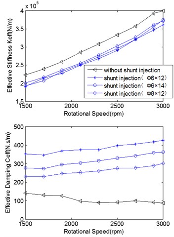
a) Rotational speed
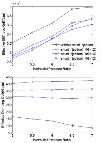
b) Inlet/outlet pressure ratio
6. Conclusions
The objective of this effort is to attempt to experimentally investigate the rotordynamic coefficients for the labyrinth seals with and without shunt injection. An improved impedance method based on the unbalanced synchronous excitation strategy was applied to identify the rotordynamic coefficients. The effect of the rotor speed and the inlet/outlet pressure ratio on the rotordynamic characteristics of the seal with and without shunt injection was analyzed. Specific findings for the cases considered include:
1) The rotating speed and the inlet/outlet pressure ratio seriously influence the stiffness and the damping coefficients of the seal with and without shunt injection. All rotordynamic coefficients increase with rotating speed and inlet/outlet pressure ratio;
2) The shunt injection contributes to decreasing the seal cross-coupled stiffness, and increasing the direct damping;
3) The shunt injection plays an important role in decreasing the effective stiffness coefficient, and increasing the effective damping coefficient. The shunt injection can effectively improve the rotor stability.
References
-
Li Zhigang, Li Jun, Feng Zhenping Numerical investigations on the leakage and rotordyanmic characteristics of pocket damper seals – part 2: effects of partition wall type, partition wall number, and cavity depth. Journal of Engineering for Gas Turbines and Power, Vol. 137, Issue 3, 2014, p. 032504.
-
Naitil J. Mehta, Childs D. W. Measured comparison of leakage and rotordynamic characteristics for a slanted-tooth and a straight-tooth labyrinth seal. Journal of Engineering for Gas Turbines and Power, Vol. 136, Issue 1, 2013, p. 012501.
-
Gao Haiping, Li Baoren, Fu Xiaoyun, Yang Gang A strong coupled fluid structure interaction solution for transient soft elastohydrodynamic lubrication problems in reciprocating rod seals based on a combined moving mesh method. Journal of Tribology, Vol. 137, Issue 4, 2015, p. 041501.
-
Kirk G., Gao R. Influence of preswirl on rotordynamic characteristics of labyrinth seals. Tribology Transactions, Vol. 55, Issue 3, 2012, p. 357-364.
-
Philip D. B., Childs D. W. Measurement versus predictions of rotordynamic coefficients of a hole-pattern gas seal with negative preswirl. Journal of Engineering for Gas Turbines and Power, Vol. 134, Issue 12, 2012, p. 122503.
-
Ertas B. H., Gvannini Delgado A. Rotordynamic force coefficients for three types of annular gas seals with inlet preswirl and high differential pressure ratio. Journal of Engineering for Gas Turbines and Power, Vol. 134, Issue 4, 2012, p. 042503.
-
Moore J. J., Soulas Thomas A. Damper seal comparison in a high-pressure re-injection centrifugal compressor during full-load, full-pressure factory testing using direct rotordynamic stability measurement. Proceedings of ASME, 19th Biennial Conference on Mechanical Vibration and Noise, Vol. 5, 2003, p. 1319-1326.
-
Naohiko T., Haruo M., Mitsuhiro N., Noriyo N. Development of scallop cut type damper seal for centrifugal compressors. Journal of Engineering for Gas Turbines and Power, Vol. 137, Issue 3, 2014, p. 032509.
-
Wagner N. G., de Jongh F. M., Moffatt R. Design testing and field experience of a high-pressure natural gas reinjection compressor. Proceedings of the 29th Turbomachinery Symposium, 2000.
-
Moore J. J., Hill D. L. Design of swirl brakes for high pressure centrifugal compressors using CFD techniques. Proceedings of the Eighth International Symposium of Transport Phenomena and Dynamics of Rotating Machinery, 2000, p. 1124-1132.
-
Nielsen K. K., Childs D. W., Myllerup C. W. Experimental and theoretical comparison of two swirl brake designs. Journal of Turbomachinery, Vol. 123, Issue 2, 2001, p. 353-358.
-
Gans B. Reverse-swirl swirl brakes retrofitting with brush seals. Turbomachinery International, 2007, p. 48-49.
-
Li Jiming, de Chouddhury Pranabesh, Kushner Frank Evaluation of centrifugal compressor stability margin and investigation of antiswirl mechanism. Proceedings of the Thirty-Second Turbomachinery Symposium, 2003, p. 49-57.
-
Riccardo D. S., Mirko M., Antonio A., Bruno F., Luca I., Alberto C. Numerical characterization of swirl brakes for high pressure centrifugal compressors. Proceedings of ASME Turbo Expo: Turbine Technical Conference and Exposition, 2013.
-
Childs D. W., James E. M. Jr., Min Z., Stephen P. A. Rotordynamic performance of a negative-swirl brake for a tooth-on-stator labyrinth seal. Proceedings of ASME Turbo Expo: Turbine Technical Conference and Exposition, 2014.
-
Childs D. W., Fozi A. An Examination of Gas Compressor Stability and Rotating Stall. NASA CP 2443, 1993.
-
Memmott E. Stability of centrifugal compressor by application of tilt pad seals, damper bearings and shunt holes. 5th International Conference of Vibrations in Rotating Machinery, 1992.
-
Park Sung-Young Computational Investigation of Fluid Injection Applications for the Gas Labyrinth. Ph.D. Thesis, Texas A&M University, College Station, TX, 2002.
-
Soto E. A., Childs D. W. Experimental rotordynamic coefficient results for (a) a labyrinth seal with and without shunt injection. Journal of Engineering for Gas Turbines and Power, Vol. 121, Issue 1, 1999, p. 153-159.
-
Kim N., Park S.-Y., Rhode D. Predicted effects of shunt injection on the rotordynamics of gas labyrinth seals. Journal of Engineering for Gas Turbines and Power, Vol. 125, Issue 1, 2003, p. 167-174.
About this article

This research was supported by the Natural Science Foundation of China (No. 11302133), Aeronautical Science Foundation of China (No. 20140454003), and Education Fund Item of Liaoning Province (No. L2013071).
