Abstract
Vibration stress relief (VSR) is an effective and economic method for reducing residual stress in various welding components. Compared with other methods, it costs much less time and energy. In this study, finite element method (FEM) was used to assist VSR treatment of large DH36 steel welded tube by determining the 1st order vibration mode of the tube and the natural frequency of the tube in a hypothetic zero-stress state. According to the computational results, proper vibration exciting assembling and excitation strategy was selected. An effectiveness index, , for fast and quantitative estimation of the residual stress decrease rate was proposed. is determined by 1st order natural frequencies of the tube in three states, i.e. as-welded, VSR treated and a hypothetic zero-stress state. in this study was 49.8 %, meeting well with the experimentally measured residual stress decrease rate, ~50 %. Thus, the validity of the effectiveness index was verified. This study provides a novel method for analysis of VSR effectiveness. In comparison, maximum residual stress was reduced by 20-57 % when traditional local post weld heat treatment (PWHT) was used. This indicates that VSR is a good stress relief method for DH36 welded structures.
1. Introduction
Vibration stress relief (VSR) of welded structures is a representative application of beneficial vibration effects. Residual stresses in welded structures commonly decrease the strength, deteriorate their fatigue performance [1, 2] and corrosion resistance [3]. The dynamic stress caused by vibration in VSR treatment promotes the propagation, lipping, and twisting of dislocations [4], especially in areas with high residual stress, inducing local yielding in the materials and relief of residual stresses. This method is time-saving and it does not deteriorate fatigue performance and corrosion resistance of the structures [5]. To date, VSR has already been used in many welded components [6, 7].
Large DH 36 steel welded structures are widely used in marine engineering, such as oil pipelines and offshore platforms. One major problem in these structures is the significant residual stresses. The most frequently used stress relief method for them is local post weld heat treatment (PWHT), in which the weld line and a limited area nearby are heated. This method costs much time and energy and may cause strength reduction of the welded joint due to phase transformation. Therefore, VSR is expected to be an alternative stress relief method. However, there are still some difficulties in applying VSR, such as optimizing frequency, exciting location selection and evaluation of treatment effectiveness. Multiple experiments are usually needed in VSR in selecting the exciting location, which are energy and time consuming especially when the structure is large. Convenient methods for assembling selection are highly desired.
The most accurate method for stress decreasing evaluation is to measure the residual stresses before and after VSR. However, direct measuring is very difficult or impossible in some circumstance. None-destructive stress measuring methods, such as X-ray diffraction method and ultrasonic methods usually require very smooth surface on the measured place, which are very difficult to realize in production. Destructive methods, such as blind-hole method, usually cost much time and are sometimes forbidden. Therefore, fast indirect effectiveness estimation method for VSR is in strong demand. Along with decrease of residual stress, natural frequency of the structure decreases. This phenomenon has been revealed for decades [8] and is currently the most popular effectiveness criteria for VSR in practice [9-11]. In the Chinese national standard JB/T5926-2005, decrease of nature frequency is listed as a feature for preliminarily estimation on whether or not the VSR treatment worked [12]. However, this criterion is empirical and qualitative because proper model has rarely been proposed. The lack of quantitative indirect estimation method greatly limited the application of VSR, and therefore, it is highly desired by researchers and engineers.
In this study, finite element method (FEM) was used to assist VSR treatment of a large DH 36 steel tube, which was made by bending and welding. Vibration exciting location were determined through a modal analysis of the tube. A novel method for quantitative estimation of stress decrease rate taking use of natural frequency only was proposed and verified. Natural frequency data obtained by FEM were used in the quantitative estimation. Traditional PWHT was conducted in another tube for comparison.
2. Materials and methods
The composition and mechanical properties of the DH36 steel are listed in Table 1 and 2. 50 mm×3000 mm×6000 mm DH 36 steel plates were bended into tubes with dimensions of Ø2000 mm×3000 mm. The gaps in the tube were filled by multi-pass welding. The filler metals were JW-1 and JM-58 (Jintai Welding Materials Co. Ltd.). Composition and mechanical properties of the filler metals are listed in the Table 3 and 4. The welding parameters are listed in the Table 5.
Table 1Composition of DH36 steel (wt.%)
C | Si | Mn | Cr | Cu | V | Ni | Nb | Fe |
0.12 | 0.18 | 1.44 | 0.08 | 0.06 | 0.07 | 0.08 | 0.037 | Bal. |
Table 2Mechanical properties of the DH36 steel
Yielding strength / MPa | Tensile strength / MPa | Ductility / % | Elastic Modulus / GPa | Poisson ratio | Density / 103 kg/m3 |
≥ 355 | ≥ 490 | ≥ 21 | 2.1 | 0.3 | 7.85 |
Table 3Composition of filler metals (wt.%)
C | Mn | Si | Si | P | Cu | Fe | |
JW-1 | 0.15 | 2.04 | 0.03 | 0.01 | 0.016 | 0.04 | Bal. |
JM-58 | 0.06 | 1.49 | 0.88 | 0.005 | 0.015 | 0.14 | Bal. |
Table 4Mechanical properties of filler metals
Yielding strength / MPa | Tensile strength / MPa | Ductility / % | Elastic modulus / GPa | Poisson ratio | Density / 103 kg/m3 | |
JW-1 | ≥400 | 550-600 | 22 | 2.0 | 0.29 | 7.73 |
JM-58 | 465 | 560 | 28 | 2.0 | 0.29 | 7.66 |
FEM was used to obtain the vibration modal of the tubes, which would assist selection of vibration excitation strategy, and natural frequency of the tubes in a hypothetical zero-stress situation, , which would be needed to establish the quantitative effective index for VSR treatment. It is not possible to obtain in experiments, as it is not possible to make such a big tube without welding. Thus, it must be obtained by FEM. Neither actual residual stress values in the tubes nor their variation after VSR were investigated in the computational study.
Fig. 1 shows the FEM model of the tube. The groove before the welding was shape, and the final cross-section shape of the weld seam was near H shape because of partial melting of the base metal. The width of the seam was ~40 mm and the thickness of the plate was 55 mm. The strength of the filler metal was much higher than the base metal, therefore, the redundant height of the weld seam was only 0-2 mm, which is neglectable comparing with the size of the seam. Since the rubber cylinders are elastic, the vibration of the tube could be considered as an approximately free vibration. Effects of gravity is neglected. Boundary conditions of the model was set as free. Because the mass of the exciter was far less than the tube, it was neglected in the model.
Table 5Welding parameters for the cylinder
Layer | Method | Filler metal | Welding current | Arc voltage (V) | Welding speed (mm/min) | ||
Ø (mm) | Type | Type | Current | ||||
Bottom | GMAW | 1.2 | JM-58 | DC (+) | 75 | 17-19 | 120-150 |
Middle 1 | SAW | 2.4 | JW-1 | DC (+) | 280-370 | 25-31 | 350-400 |
Middle 2 | SAW | 4.0 | JW-1 | DC (+) | 510-560 | 28-32 | 350-400 |
Top | SAW | 4.0 | JW-1 | DC (+) | 430-510 | 29-32 | 350-380 |
Fig. 1FEM modeling of the DH36 welded tube
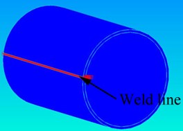
a) The whole tube
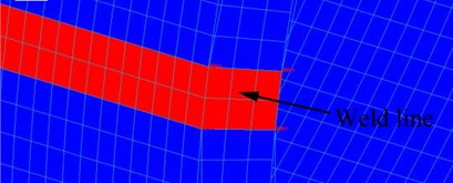
b) Area near weld seam
Modal analysis was employed to simulate the 1st order resonance of the tube. The elements of the model were all hexahedron, with 8 nodes. Total number of elements was 11175 and total number of nodes was 23864. MSC Patran® and Nastran® was used for the simulation. The materials parameters were in accordance with Table 2 and 4. The materials in the weld seam was selected as JW-1 since it occupied major spaces in the seam.
In the local PWHT, the weld line was heated to 600–650 °C on a 300 mm wide heater for 9 h, and then cooled in the air with the heater, as shown in the Fig. 2(a). The power of the heater was ~100 kW. The parameters in the local PWHT is an optimized set that was obtained from the actual manufacture procedure, which is a currently used as a typical treatment in the factory.
Fig. 2Schematics of the local PWHT experiments
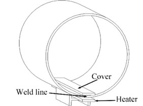
a) Assembling of the local PWHT
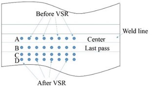
b) Locations for the residual stress measurement
According to our previous experiences and studies, the maximum residual stress commonly located in the middle and the end of the weld line. Therefore, residual stress in the middle and the end of the weld lines (~300 mm from the edge), were measured by blind-hole method before and after the PWHT/VSR treatment. Because of the limitation of time and cost, it was impossible to take multiple experiments on several tubes. To guarantee the validity of the stress measurement, 4 groups of measuring points in one place was selected before and after the treatment, respectively. Each group contained 4 points, as shown in the Fig. 2(b). A, B, C, and D are located at the center of the weld line, the center of the last pass of weld paths, weld toe, and base metal, respectively. To avoid interference between the groups, location of them was 20 mm far from each other. And the groups before and after the PWHT/VSR distributed alternately. As the tube is very large compared with the measured places, the residual stress one single place was considered as uniform. Longitudinal stress () and transverse stress () indicated the stress with directions parallel and perpendicular to the weld line, respectively.
Frequency scanning were carried out before and after the VSR treatment to obtain the corresponding natural frequency. The exciter was placed on the edge of the tube, and the frequency increased from 0 Hz to 100 Hz. The vibration power was ~1 kW. A vibration sensor was placed in the middle of the tube. An accelerometer with a piece of magnetic-iron was attached in the middle of weld line. Acceleration signals were collected by the signal acquisition system and then used to calculate displacement information by integration. Natural frequency can be determined when a peak vibration amplitude appeared in the frequency-amplitude curve. Before the VSR, the 1st order natural frequency of the tube was 53.4 Hz. In the VSR, the exciter drove the tube to vibrate at 50 Hz for 20 min. The excitation position is selected according to the FEM study, which will be described later. The power of the exciter was ~3 kW. The tube was supported by four rubber cylinders in H-shaped steel supporter. The surface vibration amplitude of the tube was 0.4-0.6 mm. After the VSR treatment, another frequency scanning was made. Residual stress variation measurement before and after the VSR treatment was similar to that after the PWHT treatment.
3. Results and discussion
3.1. Choose of vibration exciting position for VSR
Generally, the location between the exciting point and the weld line shall be carefully selected so that to maximize the vibration amplitude on the weld line. In this study, FEM analysis of vibration mode was used to assist selecting proper excitation position. Fig. 3 shows the 1st, 2nd and 3rd modal shape of the tube in the FEM simulation and the corresponding eigen-frequency was 43.9 Hz, 114.9 Hz and 212.3 Hz. The exciter could only vibrate at a frequency of 0-100 Hz, while the second order natural frequency of the tube in a zero-stress state was ~115 Hz, exceeding the maximum vibration frequency of exciter. Thus, the only practicable excitation frequency was the 1st order eigen-frequency of the tube, which was measured as 53.4 Hz. Considering natural frequency of the tube would decrease during VSR treatment, a sub-eigen-frequency, i.e. 50 Hz, was selected.
It is theoretically possible to proceed the VSR treatment at the 2nd and 3rd eigen-frequency. However, it is beyond the capacity of the equipment. And on the other hand, there are 4 peak vibration points in the 1st eigen-frequency vibration state, but 8 at the 3rd eigen-frequency. It is a common measure in VSR that the target weld seam and exciters are placed in peak vibration areas. Higher eigen-frequency vibration state causes more complicated modal shape, in which subtle error in arranging the weld seam and the exciter may cause significant variation of treatment effectiveness. Vibration in the 1st order eigen-frequency shall have better tolerance to this error because each peak vibration area has larger coverage.
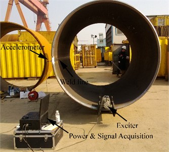
On the circle plane cross section, the vibration distributed symmetrical according to the and axis. To obtain maximum vibration amplitude, the exciter shall be attached to the tube edge. Because of the symmetrical characteristic of the vibration distribution, angle between the exciting point and the weld line on the plane can be 0°, 90° or 180°. In this study, the exciting point was selected 90° from the weld line so that to facilitate assembling VSR equipment and measuring residual stress near the weld lines. From the modal analysis, it can be seen that the vibration amplitude at the end of the tube was much higher than that in the middle. Therefore, it was expected that the decrease of residual stress shall be more significant at the end. Moreover, the 1st order natural frequency of the tube without residual stress was 43.9 Hz. This data will be used in the following quantitative analysis of residual stress decrease. Fig. 4 shows the actual assembling of VSR treatment. The exciter was tightly clamped to the tube edge and the weld line was 90° to the exciter.
Fig. 3FEM analysis of vibration amplitude of the DH36 tube
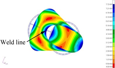
a) 1st order natural vibration
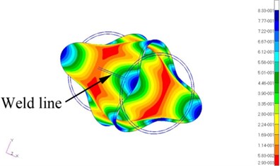
b) 2nd order natural vibration
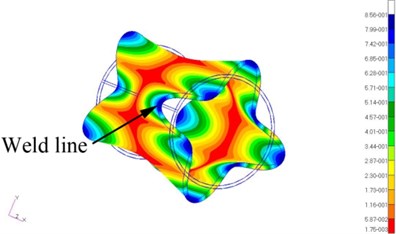
c) 3rd order natural vibration
Fig. 4Picture of the assembling of VSR treatment
3.2. Establishing a quantitative efficiency index for of VSR
It is known that stress influences natural frequency of structures [13, 14]. Residual stresses in the structures usually cause increase of stiffness and natural frequency, which is named as stress stiffening effect (SSE) [15, 16]. In the application of VSR, SSE is widely used to qualitatively estimate the effectiveness of the treatment. Generally, decrease of nature frequency of the structure indicates decrease of welding residual stress. However, this criterion is indistinct and qualitative, because quantitative relationship between the decrease rates of natural frequency and residual stress has hardly been clearly revealed yet.
Distribution of residual stress in a welded structure is complex. In the same time, natural frequency is significantly affected by the assembling, i.e. boundary conditions. Therefore, it is commonly very difficult to investigate the exact relation between residual stress and natural frequency. Fortunately, it is still possible to build quantitative model for this relation when reasonable simplification is taken into account. For a given welded structure in a specific assembling condition, an approximate parabolic relation between them is usually tenable, i.e. square of natural frequency is in linear correlation with maximum residual stress. For example, Gao et al built mathematical models of for several simple-shaped welded planes and reported parabolic formulas in several specific boundary conditions [17, 18]. Similar relation was reported by Dong [19] and Li [20] in their research on casted iron components. This relation can be considered as the preliminary mathematical foundation for evaluating stress decrease by variation of natural frequency. Based on the previous work of other researchers, we propose a half-empirical formula to depict a general relation between maximum residual stress and natural frequency:
where is the natural frequency of the welded structure, is the natural frequency of the hypothetical welded structure with zero residual stress, is a constant, and is the maximum residual stress in the structure.
can be obtained by physical simulation, or by FEM; can be measured by frequency scanning in the VSR procedure. Theoretically, when is determined, can be estimated by Eq. (1). However, is an empirical constant, which is decided by the shape and assembling of the welded structure. It is difficult to obtain its specific value. Therefore, to avoid involving this constant in the estimation, an effectiveness index was defined as:
where and is the maximum residual stress in the structure before and after the VSR treatment, respectively; and is the natural frequency of the welded structure before and after the VSR treatment, respectively. Thus, is used to indicate the decrease rate of maximum residual stress.
In the VSR treatment, the natural frequency of the welded structure before and after the VSR treatment was measured by frequency scanning. Natural frequency of the hypothetical welded structure with zero residual stress can be obtained by FEM or physical simulation, i.e. measuring the natural frequency of a structure with the same size and shape but without a weld line. FEM is apparently a more convenient and practicable choice, especially when physical simulation it is not possible as it is in this study.
It is not necessary to obtain the detailed distribution of residual stress. Further, neither the actual value of the maximum residual stress is needed (It is known that the maximum residual stress in the welded structures usually approximate yielding stress of the metal). The only indicates the decrease rate. Though it cannot be used to predict detailed variation of the residual stress, it shall be satisfactory in many situations as an improved convenient method for effectiveness evaluation of VSR.
In this study, was determined by FEM as 43.9 Hz. The natural frequency before and after the VSR treatment was 53.4 Hz and 48.9 Hz, respectively. Thus, the effectiveness index was 49.8 %. If the relationship between natural frequency and the maximum stress strictly meets Eq. (1), the decrease rate of the residual stress shall be close to 50 %.
3.3. VSR results and authentication of effectiveness index
Fig. 5 shows the variation of residual stresses in the middle of the tube. The maximum transversal stress in the as-weld tube appeared at the weld toe, approximating to the yield strength of the DH 36 steel. The residual transversal stress decreased dramatically as the distance to the weld toe increased. The longitudinal stress in the four measured locations in the as-weld tube was similar, less than 100 MPa. In general, transversal residual stress was higher than the longitudinal before the VSR treatment. This may result from the bending procedure in making the tube.
After the VSR treatment, both transversal and longitudinal residual stress in all the four measured points decreased. The maximum transversal and longitudinal residual stress before the VSR treatment were 350 MPa and 71 MPa, respectively. They were reduced to 180 MPa and 60 MPa after VSR. The corresponding decrease rate was 49 % and 15 %.
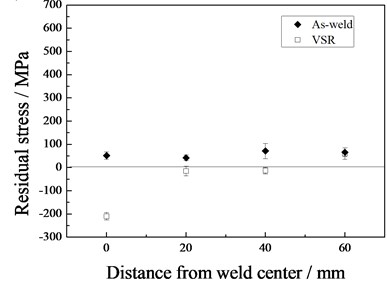
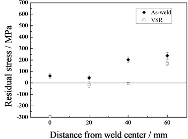
Fig. 6 shows the variation of residual stresses in the end of the tube. The transversal residual stress was higher than the longitudinal before the VSR treatment. Comparing with Fig. 5, the longitudinal stress at the end is much higher than that in the middle. The maximum transversal stress in the as-weld tube appeared at the weld center, approximating to the yield strength of the DH 36 steel. The residual transversal stress decreased dramatically as the distance to the weld center increased. The maximum longitudinal stress in the as-weld tube appeared at the weld center and residual transversal stress decreased dramatically as the distance to the weld center increased.
After the VSR treatment, both transversal and longitudinal residual stress in all the four measured points decreased. The maximum transversal and longitudinal residual stress at the tube end before the VSR treatment were 358 MPa and 243 MPa, respectively. They were reduced to 190 MPa and 65 MPa after the VSR treatment. The corresponding decrease rate was 47 % and 73 %.
The effect of VSR is better in the end of the tube than in the middle when variation of longitudinal stress is taken into account. This is in accordance with the vibration amplitude distribution obtained by FEM and the residual stress distribution in the as-weld tube. Mechanism of VSR is the local yielding caused by the overlying of residual stress and vibration dynamic stress. Vibration amplitude and the residual stress at the end of the tube were much higher than these in the middle, therefore, the decrease rate of residual stress was more significant.
Fig. 5Residual stress in the tube middle before and after VSR
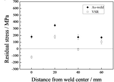
a) Transversal residual stress
b) Longitudinal residual stress
Concerning the maximum residual stress before and after the VSR treatment, i.e. the maximum transversal residual stress, effect of VSR in the two places in the middle and end of the tube was 47 % and 49 %, respectively. That is very satisfactory according to the requirement of manufacturing. Moreover, the experiment results met well with the estimation made with . The indicated a 49.8 % decrease of maximum stress, which was very close to the measured values. The slight difference between the experiment data and the estimation may result from error of the measurement or the half-empirical model. Thus, the validity of was verified.
The effectiveness index can be conveniently used in VSR treatment. Simple FEM model is needed to obtain the natural frequency in a zero-stress state and the natural frequencies before and after VSR can be easily obtained through frequency scanning. Based on these data, effectiveness of the VSR treatment can be quickly estimated. Thus, effectiveness evaluation by time-consuming stress measurement after VSR can be partially or even totally replaced. Moreover, this method can possibly be used for effectiveness evaluation of other stress relief methods. Application of this index is expected to be further studied in a wilder area in the future.
Fig. 6Residual stress in the tube end with and without VSR

a) Transversal
b) Longitudinal
3.4. Comparison with local PWHT
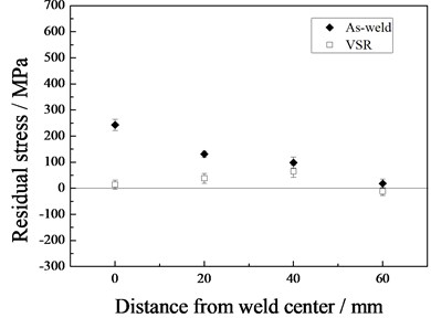
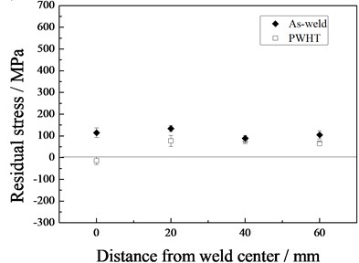
Fig. 7 shows the variation of residual stresses in the middle of the weld line. The maximum transversal stress in the as-weld tube appeared at the weld toe, approximating to the yield strength of the steel. The residual transversal stress decreased dramatically as the distance to the weld toe increased. The longitudinal stress in the four measured locations in the as-weld tube was less than 150 MPa. In general, the transversal residual stress was higher than the longitudinal before the VSR treatment.
After the PWHT treatment, both transversal and longitudinal residual stress in all the four measured points decreased. The maximum transversal and longitudinal stress before the PWHT was 355 MPa and 134 MPa, respectively. After the treatment, they were reduced to 154 MPa and 77 MPa. The reduction rate was 57 % and 43 %, respectively. Location of the maximum transversal and longitudinal stress was the center of the last weld path.
Fig. 7Residual stress in the tube middle with and without TSR
a) Transversal
b) Longitudinal
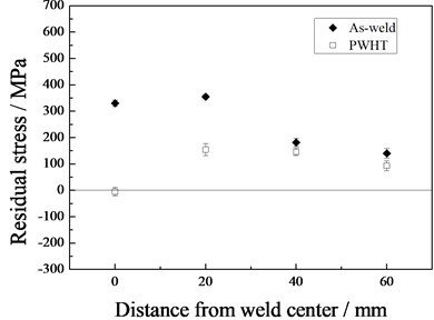
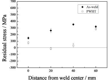
Fig. 8 shows the variation of residual stresses in the end of the weld line. The transversal residual stress was higher than the longitudinal before the PWHT treatment. The maximum transversal stress in the as-weld tube appeared in the heat affected zone, approximating yield strength of the steel. The maximum longitudinal stress appeared in the heat affected zone. Comparing with Fig. 7, the longitudinal stress at the end is higher than that in the middle.
After the PWHT treatment, both transversal and longitudinal residual stress in all the four measured points decreased. The maximum transversal and longitudinal stress before the PWHT was 353 MPa and 238 MPa, respectively. After the local PWHT, they were reduced to 284 MPa and 170 MPa. The reduction rate was 20 % and 29 %, respectively.
Thermal stress relief and VSR are often compared by researchers and each of them has its own advantages and disadvantages. Most researches on VSR emphasize its high efficiency and low cost of time and energy [5, 21], especially when the structures are very large in size. In this study, the time and energy consumption of VSR was less than 1/10 of PWHT, and the effect was better. Therefore, it is reasonable to conclude that VSR is a very promising method for stress relief of welded DH 36 steel marine engineering structures. Further study on applications on these structures will be carried out in the future. Methods for stress relief shall be chosen according to the specific demand in practice.
Fig. 8Residual stress in the tube end with and without PWHT
a) Transversal
b) Longitudinal
4. Conclusions
In the large tubes made by bending and welding, significant residual stresses in two directions existed in areas near the weld line. The primary stress was transversal stress. VSR and traditional local PWHT were used to release the residual stress. FEM was employed to analyze the vibration characteristics of the tube, and to assist selecting proper VSR assembling.
Effectiveness index of VSR treatment, , was proposed for the first time, by which a fast and quantitative effectiveness estimation can be made right after the treatment. The maximum stress decrease rate of the tube indicated by the effectiveness index was 49.8 %, and the measured decrease rate of maximum residual stress was 47-49 %. Further study on this efficiency index in other structures will be carried out in the future.
The effect of VSR was equivalent to or slightly better than PWHT in the given situations in this study. The time and energy consumed in VSR were less.
References
-
Laamouri A., Sidhom H., Braham C. Evaluation of residual stress relaxation and its effect on fatigue strength of AISI 316L stainless steel ground surfaces: experimental and numerical approaches. International Journal of Fatigue, Vol. 48, Issue 2, 2013, p. 109-121.
-
Biallas G. Effect of welding residual stresses on fatigue crack growth thresholds. International Journal of Fatigue, Vol. 50, Issue 6, 2013, p. 10-17.
-
Van B. G., Chen W., Rogge R. The role of residual stress in neutral pH stress corrosion cracking of pipeline steels. Part I: pitting and cracking occurrence. Acta Materialia, Vol. 55, Issue 1, 2007, p. 29-42.
-
Walker C. A., Waddell A. J., Johnston D. J. Vibratory stress relief – an investigation of the underlying processes. Proceedings of the Institution of Mechanical Engineers Part E: Journal of Process Mechanical Engineering, Vol. 209, Issue 15, 1995, p. 51-58.
-
Munsi A., Waddell A. J., Walker C. A. The influence of vibratory treatment on the fatigue life of welds: a comparison with thermal stress relief. Strain, Vol. 37, Issue 4, 2001, p. 141-149.
-
Sun M. C., Sun Y. H., Wang R. K. Vibratory stress relieving of welded sheet steels of low alloy high strength steel. Mater Letters, Vol. 58, Issue 7, 2004, p. 1396-1399.
-
Rao D., Wang D., Chen L., Ni C. The effectiveness evaluation of 314L stainless steel vibratory stress relief by dynamic stress. International Journal of Fatigue, Vol. 29, Issue 1, 2007, p. 192-196.
-
Chu J. Y., Chen L. G., Ni C. Z. Comparison of several methods for evaluating effectiveness of vibration stress relief process. Transactions of the China Welding Institution, Vol. 24, Issue 1, 2003, p. 57-60.
-
Han Y. Z., Liu A. M. Research on evaluation methods for effect of vibration stress relief. Hot Working Technology, Vol. 42, Issue 16, 2013, p. 217-220.
-
Dawson R., Moffat D. G. Vibratory stress relief: a fundamental study of its effectiveness. Journal of Engineering Materials and Technology, Transactions of the ASME, Vol. 102, Issue 1, 1980, p. 169-176.
-
Klauba B. B., Adams C. M., Berry J. T. Vibratory stress relief: methods used to monitor and document effective treatment, a survey of users and directions for further research. 7th International Conference on Trends in Welding Research, Pine Mountain, GA, United States, 2005.
-
JB/T5926-2005. Vibration Stress Relief Effect-Evaluation Methods. Chinese National Machinery Professional Standard, 2005.
-
Almeida J. F. M., Hansen J. S. Natural frequencies of composite plates with tailored thermal residual-stresses. International Journal of Solids and Structures, Vol. 36, Issue 23, 1999, p. 3517-3539.
-
Su R., Wang B., Ding W., Zhu L. Influence analysis of stress stiffening effect of rotating wheel-disc on its modal characteristics. Journal of Engineering Design, Vol. 16, Issue 4, 2009, p. 292-291.
-
Flores J. E. R., Viana F. A. C., Rade D. A. Identification of external forces in mechanical systems by using LifeCycle model and stress-stiffening effect. Mechanical Systems and Signal Processing, Vol. 21, Issue 7, 2007, p. 2900-2917.
-
Wang L., Guo M., Guo Y. Nature frequency calculation of revolving parts considering stress stiffening and spin softening. Applied Mechanics and Materials, Vol. 427, Issue 429, 2013, p. 33-36.
-
Gao Y., Lin L. Natural frequency of component under influence of welding residual stress. Transactions of Nonferrous Metals Society of China, Vol. 6, Issue 1, 1996, p. 135-140.
-
Gao Y., Tang G., Wan W. Natural frequencies calculation of a quadrate thin plate with welding residual stress. Journal of Vibration and Shock, Vol. 33, Issue 9, 2014, p. 165-167.
-
Dong X., Ren D., Wang D., Zhai Y. Effect of residual stress in ductile iron component on its natural frequency. Advanced Materials Research, Vol. 308, Issue 310, 2011, p. 967-72.
-
Li W., Dong X., Wang D., Ren D. Study on the relation between residual stress and natural frequency of cast iron components. Journal of Zhongyuan University of Technology, Vol. 18, Issue 2, 2007, p. 7-10.
-
Claxton R. A. Vibratory stress relieving – an effective alternative to thermal-treatment for component stabilization. Heat Treatment of Metals, Vol. 18, 1991, p. 53-59.
Cited by
About this article

Shuqi Li proposed the concept of effectiveness index, designed the experiments, carried out major job of FEM study, data analysis and paper drafting. Hongyuan Fang supervised the research work and guided the research mentality. Xuesong Liu organized the experiments tasks and participated in the manuscript drafting. Qiang Wang and Wei Wang undertook the stress relief treatments and residual stress measuring by blind hole method. Wei Cui participated in designing of experiments, drafting of the manuscript, stress relief treatments and residual stress measuring.
