Abstract
The multiple-root resonance theory is introduced. The multiple-root resonance region is defined, and it includes the sub-multiple-root resonance region and complete-multiple-root resonance region. It is proved that the vibration mode shapes are identical if the natural frequencies are similar in size. The dynamic analysis of the 3-DOF model is investigated, and the results show that the variations of the mass ratio and stiffness ratio induce the natural frequencies approaching and forming a multiple-root resonance. The dynamic analysis of the tandem mill is made to study the multiple-root vibration, and the results show that with the increase in mass ratio, the 6th and 7th-order natural frequencies continue approaching one another and converge at the 5th-order natural frequency. The finite element analysis of the rolling mill shows that there are two similar natural frequencies in the rolling mill, and the vibration modes are not identical but have large vertical-component vibrations. The field test shows that the multiple-root resonance occurs in the tandem mill; after the foundation reconstruction, the multiple-root resonance is replaced by resonance with one dominant frequency, and the vibration is reduced.
1. Introduction
Rolling mill vibration can reduce the life of equipment and can affect the product quality, which is a worldwide problem and has attracted the attention of many scholars. Yarita, Tlusty, etc. [1, 2] studied the rolling mill vibration theoretically and explored its vibration mechanism; Tamiya T., Furui K. and Lida H. [3] studied the flutter phenomenon in the cold rolling process; Roberts W. [4] deeply discussed the triple-frequency flutter of the rolling mill; Nessler [5] studied the five-frequency flutter mode of the four-high rolling mill; Johnson [6] considered the non-linear factors of the rolling mill vibration; Chinese scholar Yan Xiaoqiang found that the rolling mill vibration was induced by the combination of mechanical, electrical and hydraulic movements [7].
Absorber can effectively suppress vibration, and it has attracted a large amount of attention: Rao [8] thought that hybrid dampers were more effective and reliable than a single active damper or passive dampers; J. studied the efficiency of the Semi-active Absorber for Controlling Self-excited Vibration [9]. In the field of rolling vibration research, Wang Xinxin and Yan Xiaoqiang [10] used the active vibration suppressor on the rolling mill [11] and achieved a good vibration suppression effect.
Scholars have made many achievements in the rolling mill vibration mechanism and vibration suppression. However, when solving the inherent characteristics of the rolling mill, few people pay attention to the essence of the rolling mill natural frequency. In this paper, the entire tandem mill is taken as a research object, the foundation mass of the tandem mill is considered as a variable, and the relationship between the foundation mass of the tandem mill and the natural frequency of the system is dynamically observed. Then, it was found that the natural frequency of the resonance of the tandem mill was caused by the combined action of one or more groups of multiple-root natural frequencies, which implied that the essence of the resonance of the rolling mill was a multiple-root resonance. In terms of vibration suppression, it was proposed to consider the multiple-root resonance in the design stage to avoid the existence of two or more approximate natural frequencies in the tandem mill.
2. Theory
2.1. Definition of multiple-root resonance
According to the vibration theory [11], when the excitation frequency is included by the resonance region of the system, the resonance will occur. When there are two close natural frequencies and in a system, the resonance region of each natural frequency is described by the neighbourhood as follows:
where is the natural frequency of the system, and is the neighbourhood radius of the natural frequency , which is positive. When the excitation frequency is included by the resonance region of a natural frequency of the system, the resonance will occur.
It is assumed that the two adjacent natural frequencies are and and . The neighbourhood of the two adjacent frequencies is shown in Eq. (1). Then, we have the intersection of these regions:
where is the intersection of two natural frequency resonance regions. If the excitation frequency , the two resonance frequencies will be excited, and two natural modes will simultaneously occur. If two resonance frequencies are similar or equal, the corresponding natural modes are identical. In the case of , it is known from the principle of linear superposition that the system will vibrate more violently than the resonance with a single natural mode. The vibration, where two or more natural modes are excited by the same source, is called as a “multiple-root resonance”, and the neighborhood intersection is called as the “multiple-root region”.
If , but their values are similar, they are called as a pair of “sub-multiple roots”, and is called as the “sub-multiple-root region”. If , the characteristic equation has multiple roots in the analytic solution, which are called as the “complete-multiple-root” here, and is called as the “complete-multiple-root region”. This paper only studies the sub-multiple-root.
The definition of the “multiple-root region” of multiple frequencies is similar.
2.2. Vibration mode of “multiple-root resonance”
This section proves that when the two natural frequencies are similar enough by their value, their vibration modes are consistent. The matrix in the dynamic equation for the multi-DOF vibration system is as follows [11]:
where is the stiffness matrix; is the mass matrix; is the eigenvector. When is substituted, Eq. (3) is transformed to:
where (1, 2, 3, 4) is the element of ; is the element of matrix , and:
where , and are the corresponding elements of matrices and ; Eq. (4) has a nonzero solution, and matrix is not a full-rank matrix. According to the elementary transformation of matrix [12], matrix can be transformed into a trapezoidal matrix :
where is the element of the transformed matrix . For the convenience of discussion, it is assumed that the system does not have an analytic multiple root; so that only the th row of the trapezoidal matrix is zero, and the first rows of Eqs. (4) and (5) are equal. The second lines of are:
where and are elements of each row of and .
Every element, , in the matrix has a quadratic continuous function for . From Eq. (6), we know that the operation of is a simple operation of addition, subtraction, multiplication and division in the trapezoidal transformation process. Therefore, according to the theorem of continuous function [13], it is known that is a continuous function, so the following can be obtained:
The linear equations of Eq. (5) are:
According to the final equation of Eq. (8), the following can be obtained:
where is the vibration mode. With substitution and iteration, the corresponding mode of natural frequency is as follows:
Suppose that the system has two natural frequencies: , , and , where is infinitesimal. Their modes are:
With Eqs. (7) and (9), the following can be obtained:
Similarly, it can be proven that . Therefore, when the natural frequencies, and , are similar by their value (the difference between them is tiny enough), the following can be obtained:
Thus, when the system has two natural frequencies with very similar values, the mode shapes are identical. And if two natural frequencies are induced by an excitation frequency, the multiple-root resonance occurs, and the superposition of the identical mode shapes amplifies the vibration.
2.3. Dynamics study of multiple-root vibration
In this section, the “device-foundation” dynamic model is introduced to study the multiple-root vibration. This model is shown in Fig. 1.
Fig. 1Dynamic model of “device-foundation” system
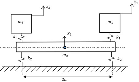
It is assumed that the foundation does not swing. For Fig. 1, the dynamic equations are as follows:
The characteristic equation of Eq. (14) is:
The changing mass and stiffness have a great significance in discussing the “multiple-root”.
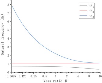
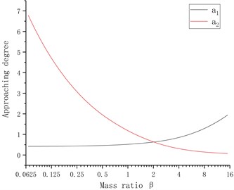
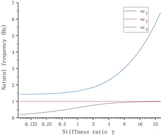
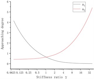
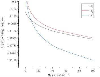
Thus the mass ratio is considered as a variable, and 1 kg, 1 N/m, is substituted, the multiple-root natural frequency of the equipment when the mass ratio changes is discussed; and then the stiffness ratio is considered as a variable, and substituted 1 kg, 1 N/m, , , then the “multiple-root” of the system is discussed when the stiffness varies. The relationships among the mass, stiffness and natural frequency are shown in Fig. 2, where is the approaching degree between and ; is the approaching degree between and , and is defined. Fig. 2 shows that when the mass ratio increases, the 2nd-order natural frequency and 3rd-order natural frequency continue approaching, and when , the approaching factor , when the stiffness ratio increases, the 1st-order natural frequency and 2nd-order natural frequency are gradually approaching one another, and when , the approaching factor 0.013, and will continue to decrease with the increase in stiffness ratio.
Fig. 2Relationship among mass ratio, stiffness ratio and root natural frequency
3. Multiple-root resonance of tandem mill
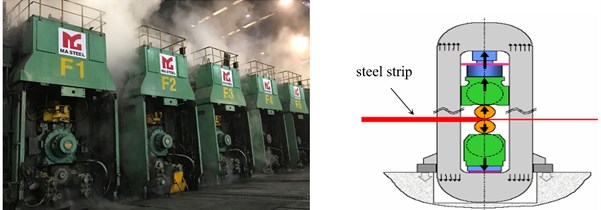
Tandem mills, including hot tandem mills and cold tandem mills, are used for steel strip production, as shown in Fig. 3.
The tandem mill is a typical “multi-device-foundation” system as shown in Fig. 1, which has 5 stands installed on the foundation.
Fig. 3Tandem mill and separate stand
3.1. Dynamics analysis of tandem mill
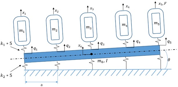
According to Fig. 3, a simplified diagram of the tandem mill is shown in Fig. 4, where (1, 2, 3, 4, 5) is the DOF of each mill, and is the DOF of the foundation; (1, 2, 3, 4, 5) is the DOF of each connect region, and ; (1, 2, 3, 4, 5) is the quality of each stand; is the quality of the foundation; is the moment of inertia of the foundation; is the connection stiffness of each mill and foundation; is the stiffness of the foundation and earth; a micro-pendulum motion around the center of the foundation is considered in the system, and is the pendulum angle; is the harmonic excitation, and , is the amplitude; is the distance between two stands. There are seven DOFs in the system, and vector is defined as the DOFs of the system:
The dynamics equations of Fig. 4 are:
The mass matrix is:
The stiffness matrix is:
The characteristic equation is:
From the literature [14] and field measurement, we have: 4.152×10⁹ N/m, 2.36×10⁷ N/m. The inertia of the foundation is:
where is the height of the foundation, and is the length between two stands. From the design, it is possible to obtain 9.6 m, 5.5 m. Because the quality of each stand of the tandem mill approaches 444000 kg according to the field data, it is supposed 444000 kg. The mass of the foundation is about 20 times that of the rolling mill according to the field data, thus, it is supposed as 8880000 kg.
Fig. 4Simplified diagram of tandem mill
3.2. Multiple-root resonance of tandem mill
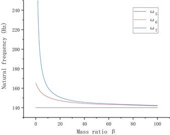
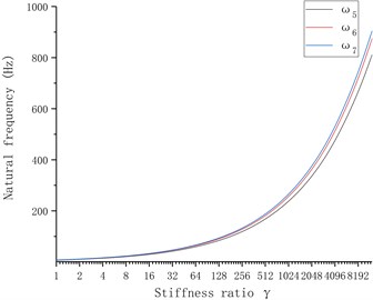
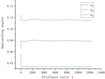
When the mass of the foundation, , is considered as a variable, ( is the mass ratio) is defined and , , , , , , and are substituted to Eq. (20); when the stiffness is considered as a variable, ( is the stiffness ratio) is defined, and the above parameters are substituted to Eq. (20). The relationship among , and the natural frequencies of the system are obtained by numerical calculation as shown in Fig. 5, where is the approaching degree between and ; is the approaching degree between and ; is the approaching degree between and , and the equation is defined as follows: . Fig. 5 shows that when is considered as a variable, the 6th- and 7th-order frequencies of the mill gradually approach and converge to the 5th-order frequency, and the approaching degree of the 6th and 7th-order frequencies, , is minimal; when is considered as a variable, the proximity factor has little variation, thus the mass ratio is only considered.
The foundation mass of the tandem mill in one steel factory is 20 times of that of a single mill (). Then, the 6th- and 7th-order natural frequencies are 147 Hz and 150 Hz, and the proximity factor between them is 2.4 %. It is easy to form the multiple-root region and initiate the multiple-root resonance.
Fig. 5Relationship among natural frequency, mass ratio and stiffness ratio of rolling mill
3.3. Modal analysis of multiple-root resonance
The modal analysis of the tandem mill is performed with ANSYS workbench. The results are shown in Fig. 6.
Fig. 6 shows that the tandem mill has two natural frequencies with similar value: 142.93 Hz and 144.33 Hz, and the corresponding vibration modes are different but have large vertical components: the maximum vibration amplitudes occur on F5 and F4, respectively. Therefore, if the tandem mill is excited with a frequency approach to 142 Hz and 144 Hz, two natural modes will be simultaneously excited and initiate the multiple-root resonance.
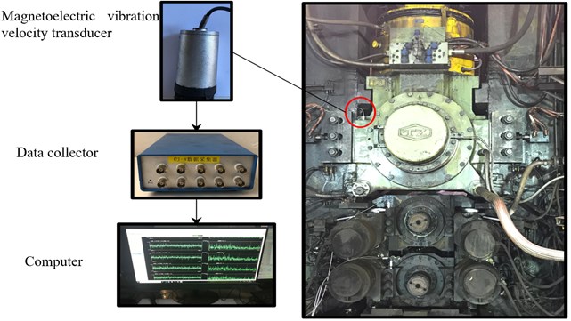
3.4. Field test of multiple-root resonance of tandem mill
The beat vibration is the superposition of two or more signals with similar frequencies and amplitudes, and these signals are characterized with strong-weak cycles, therefore, the spectrum of the beat vibration shows two or more dominant frequencies approach each other. Many studies show that, one of these dominant frequencies in the beat vibration is the excitation frequency. However, in the study of tandem mill vibration, it is found that the two dominant frequencies approach each other due to that they are both natural frequencies, and make a pair of “sub-multiple-root”. To verify that the “sub-multiple-root” exists in the tandem mill, the mill vibration was tested before and after the foundation modification which reduced the mass of the whole foundation and turned the mass ratio of the foundation and the single mill from 20 to 17.5. Magnetoelectric vibration velocity transducers and data collector were used in the field test, and the parameters of the sensor and collector are shown in Table 1 and Table 2, respectively.
Fig. 7 shows the test position in field.
Fig. 6Mode of continuous rolling mill
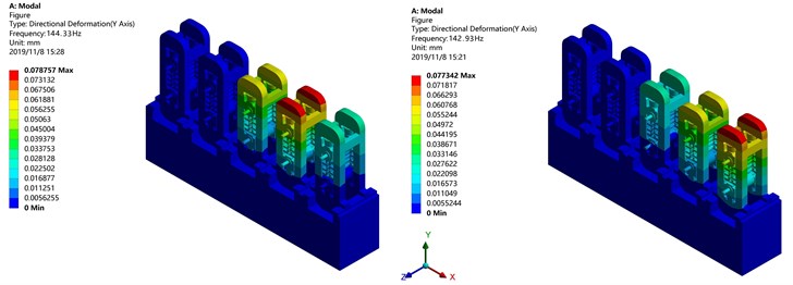
Table 1Sensor parameters
Technical specifications | Value |
Frequency response range | 1 Hz-500 Hz |
Sensitivity | 28.2 mV/(mm/s) |
Table 2Data collector parameters
Technical specifications | Value |
Bandwidth | 1 Hz-10 kHz |
Maximum analysis frequency | 100 kHz |
Rotation rate range | 0.01-400.00 rpm |
Fig. 7Field test site and testing instruments
The vibrations of F4 and F5 before and after the reconstruction of foundation are shown in Fig. 8 and Fig. 9, respectively.
Fig. 8 shows that both F4 and F5 stands have an obvious double-beat vibration with the frequencies of 142 Hz and 144 Hz, which are almost identical to the two natural frequencies in the simulation in section 3.3. The excitation frequency is 138 Hz, which approaches two dominant frequencies of F5 stand. From Fig. 8, it can be seen that F5 stand has a larger vibration than F4.
Fig. 9 shows that after the foundation reconstruction, F4 and F5 stands have one dominant frequency of 132 Hz. The excitation frequency of 138 Hz remains in the spectrum of F5.
Fig. 8Vibration spectrum before foundation reconstruction
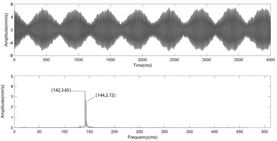
a) Vibration spectra of F4 stand
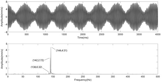
b) Vibration spectra of F5 stand
Fig. 9Vibration spectrum after foundation reconstruction
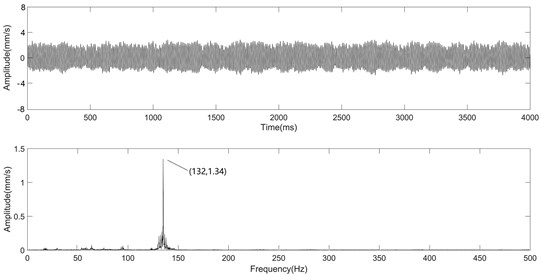
a) Vibration spectra of F4 stand
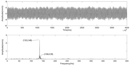
b) Vibration spectra of F5 stand
Comparing the time domain waveforms of Fig. 8 and Fig. 9, it can be seen that the multiple-root resonance of the mill is much more violent than that of the mill with the resonance as one dominant frequency. After the foundation reconstruction, the mass ratio is changed, and the gap between the two natural frequencies, which are a pair of “sub-multiple-root” before the reconstruction, widens. Then, only one natural mode is induced by the excitation, thus, the vibration is reduced.
4. Conclusions
1) The theory of “multiple-root resonance” is introduced, and the “multiple-root region” is defined. Vibration mode of the “multiple-root resonance” is analyzed, and it is concluded that when the system has two natural frequencies with very similar value, and the corresponding modes are identical.
2) “Device-foundation” dynamic model is introduced to analyze the relationship among the mass ratio, stiffness ratio and the natural frequency, the results give the basis to conclude that the natural frequencies vary when the mass ratio or stiffness ratio varies, in some case the natural frequencies approach each other and result to “multiple-root”.
3) A theoretical analysis, finite element simulation and field test show that the multiple-root resonance existed in the tandem mill, which has never been noticed in the past. By comparing with the vibration spectra before and after the foundation modification, it was concluded that the multiple-root resonance of the mill is much more violent than the mill with the resonance as one dominant frequency. Thus, it was suggested that in the design stage of the tandem mill, it was necessary to consider the mass ratio of the foundation and single mill to avoid the multiple-root resonance, which was very instructive to the design of tandem mills.
References
-
Yarita I., Furukawa K., Seino Y. Analysis of chattering in cold rolling of ultrathin gauge steel strip. Transactions of the Iron and Steel Institute of Japan, Vol. 18, Issue 1, 1978, p. 1-10.
-
Tlusty J., Critchley S., Paton D. Chatter in cold rolling. Annals of the CIRP, Vol. 31, Issue 1, 1982, p. 195-199.
-
Tamiya T., Furui K., Lida H. Analysis of chattering phenomenon in cold rolling. C. Proceedings of science and technology of flat rolled products. International Conference on Steel Rolling, Vol. 2, 1980, p. 1191-1207.
-
Roberts W. Third-octane-mode chatter in the cold rolling of light gauge strip. C. Proceedings of Science and Technology of Flat Rolled Products. Tokyo: International Conference on Steel Rolling, Vol. 2, 1980, p. 1215-1224.
-
Nessler G. L., Cory J. F. Cause and solution of fifth octave back-up roll chatter on 4-hold mills and temper-mills. Iron and Steel Engineer, Vol. 66, Issue 12, 1989, p. 33-37.
-
Johnson R., Qi Q. Chatter dynamics in sheet rolling. International Journal of Mechanical Sciences, Vol. 36, Issue 7, 1994, p. 617-630.
-
Yan Xiaoqiang Machinery electric-hydraulic coupling vibration control of hot continuous rolling mills. Journal of Mechanical Engineering, Vol. 47, Issue 17, 2011, p. 61-65.
-
Hanumantha Rao T. V., Srinivasa Rao M. S. S., Apparao B. V., et al. Study on design and analysis of hybrid vibration damper with energy harvesting and optimal damping effect. Journal of The Institution of Engineers (India): Series C, Vol. 95, 2014, p. 97-102.
-
Mondal J., Chatterjee S. J. Inst. Efficacy of semi-active absorber for controlling self-excited vibration. Journal of The Institution of Engineers (India): Series C, Vol. 101, 2020, p. 97-103.
-
Wang X., Yan X. Active vibration suppression for rolling mills vibration based on extended state observer and parameter identification. Journal of Low Frequency Noise, Vibration and Active Control, 2019, https://doi.org/10.1177/1461348419850370.
-
Rossing Thomas D., Fletcher Neville H. Principles of Vibration and Sound. Springer-Verlag, New York, 1995, p. 23-46.
-
David Harville A. Matrix Algebra: Exercises and Solutions. Springer-Verlag New York, 2001, p. 7-28.
-
Potter Merle C., Lessing Jack L., Aboufadel Edward F. Advanced Engineering Mathematics. Springer Nature, Switzerland, 2019, p. 22-63.
-
Pedersen N. L., Pedersen P. On pre-stress stiffness analysis of bolt-plate contact assemblies. Archive of Applied Mechanics, Vol. 78, Issue 2, 2008, p. 75-88.
About this article

